The outcomes of this lab: 1. Be able to interface your
MCU with an ESP8266 module. 2. Be able to transfer the
sensor's data to ESP8266 and display it on ThingSpeak. 3. Be able to prototype a
commercial product using MCUs, sensors, IoT platforms, and PCBs. 4. Be able to interface your
Arduino NANO with the DS18B20 temperature sensor and the ssd1306 OLED
module 1. Introduction to the DS18B20
temperature sensor
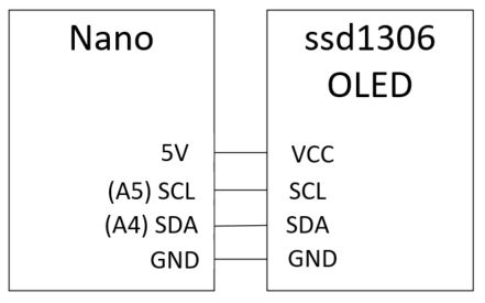
1.1. Get started with Arduino Nano and the ssd1306 OLED module
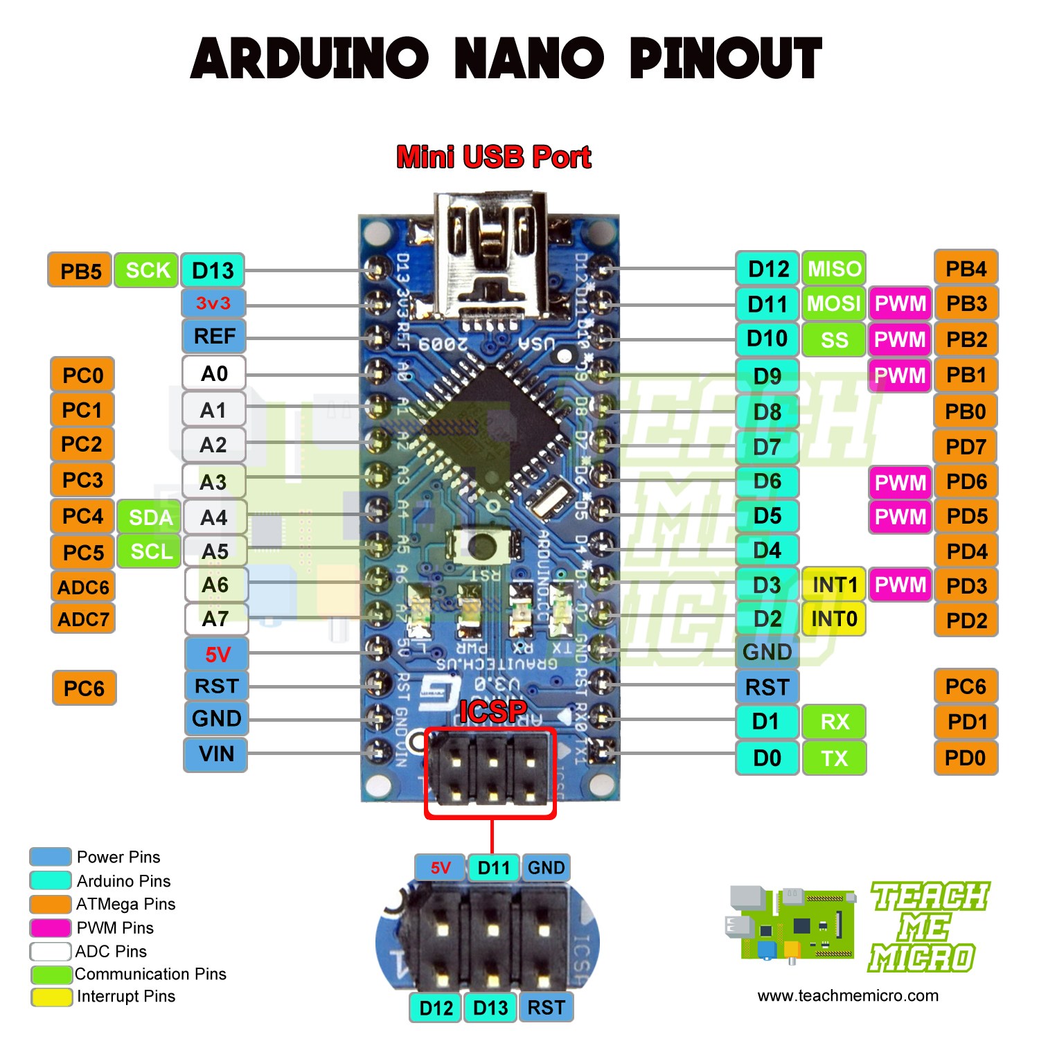
Arduino Nano Featured snippet from the web The Arduino Nano is a small,
complete, and breadboard-friendly board based on the ATmega328 (Arduino
Nano 3. x). It has more or less the same functionality of the Arduino
Duemilanove, but in a different package. It lacks only a DC power jack,
and works with a Mini-B USB cable instead of a standard one.
Check the Arduino product page Arduino Nano where it clearly states
"Operating Voltage (logic level) 5V". Apart from that many Arduino
boards have a 3V3 regulated output that can be used to supply an
external circuit when required.
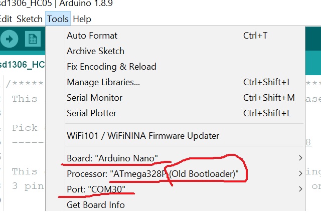
In your Arduino IDE, check if you have selected the correct Board,
Processor, and Port.
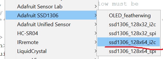
In File - Examples, you should see the Adafruit GFX Library and the
Adafruit SSD1306 library.
In Adafruit SSD1306, you should select the ssd1306_128x64_i2c option.
The OLED module in your box has 128x64 pixels and the communication
protocol is I2C, so you are expecting to see an SDA and an SCL pin on
the board.
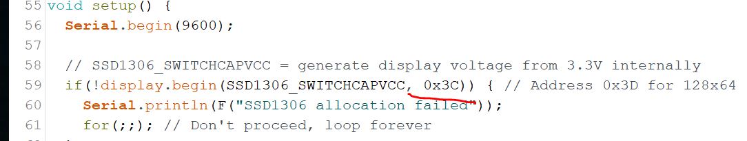
Load the example code in your IDE, COPY and PASTE the code to your
sketch (Do not directly modify the example code!!!!!!!!!).
In the code, change the device address from 0x3D to 0x3C.
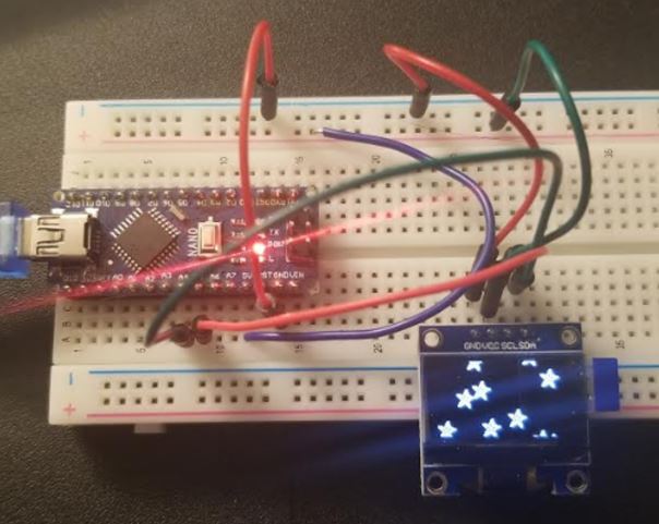
Upload the code, it should show the demonstration animation, images,
and texts on your OLED.
A demonstration video:
In this experiment we only need the text display function so let's get rid of all the redundant functions in the sketch.
// Declaration for an SSD1306 display connected to I2C (SDA, SCL pins) #define OLED_RESET 4 // Reset pin # (or -1 if sharing Arduino reset pin) Adafruit_SSD1306 display(SCREEN_WIDTH, SCREEN_HEIGHT, &Wire, OLED_RESET);
void setup() { Serial.begin(9600); // SSD1306_SWITCHCAPVCC = generate display voltage from 3.3V internally display.begin(SSD1306_SWITCHCAPVCC, 0x3C);// Address 0x3C for 128x64 testdrawchar(); // Draw characters of the default font testdrawstyles(); // Draw 'stylized' characters }
void loop() { }
void testdrawchar() { display.clearDisplay(); display.setTextSize(1); // Normal 1:1 pixel scale display.setTextColor(SSD1306_WHITE); // Draw white text display.setCursor(0, 0); // Start at top-left corner display.cp437(true); // Use full 256 char 'Code Page 437' font
// Not all the characters will fit on the display. This is normal. // Library will draw what it can and the rest will be clipped. for(int16_t i=0; i<256; i++) { if(i == '\n') display.write(' '); else display.write(i); } display.display(); delay(2000); }
void testdrawstyles() { display.clearDisplay(); display.setTextSize(1); // Normal 1:1 pixel scale display.setTextColor(SSD1306_WHITE); // Draw white text
display.setCursor(0,0);
// Start at top-left corner display.println(F("Hello, world!")); display.setTextColor(SSD1306_BLACK, SSD1306_WHITE); // Draw 'inverse' text display.println(3.141592); display.setTextSize(2); // Draw 2X-scale text display.setTextColor(SSD1306_WHITE); display.print(F("0x")); display.println(0xDEADBEEF, HEX); display.display(); delay(2000); }
Upload it to the board and you will only see the text demonstrations.
Task
1.1: Repeat this
example on your side. (5 points)
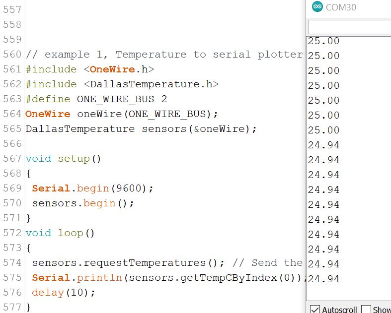
1.2 Read the temperature from DS18B20 (datasheet) from your Arduino Nano board
Sensors comments/details from
the vendor on Amazon: *Sealed with epoxy resin,
high thermal conductivity, impact resistance, high water
resistance,High quality 304 stainless steel housing,High quality
environmentally friendly pure copper wire 3*7/0.15 *The probe uses a
new original imported DS18B20 temperature sensor chip,each pin of chip
is separated by heat shrink tube to prevent short circuit,26AWGPVC wire *Waterproof and
moisture,Fast temperature sensing, accurate temperature
measurement,Output lead:red (VCC), yellow(DATA) , black(GND) *Wide range of product
applications: refrigerators, air conditioners, freezers, cable
trunking, etc.The temperature signal can be directly converted into a
serial digital signal for processing by the microcomputer *Cable length:Approx.300 cm
,Stainless steel tube length: 50mm
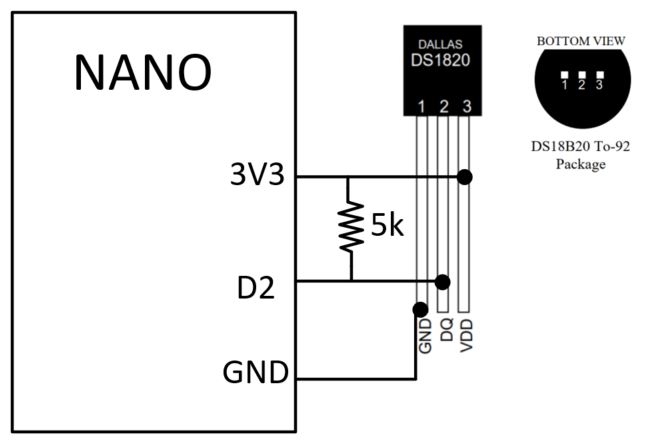
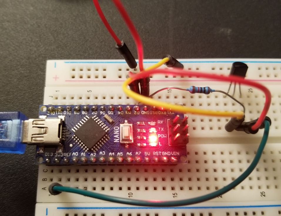
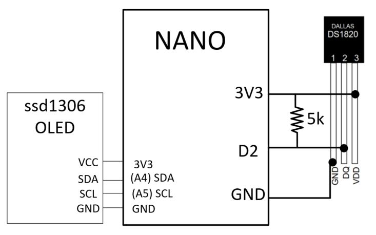
Make the following connections: Use a 5 k resistor to replace
the 4.7 k resistor is fine, it is just a pull-up resistor.
Make this connection on your
breadboard:
Download the these two
libraries (onewire.zip, and milesburtonTemp.zip) and unzip them. Put the
unzipped folders at the following location: C:\Program Files
(x86)\Arduino\libraries
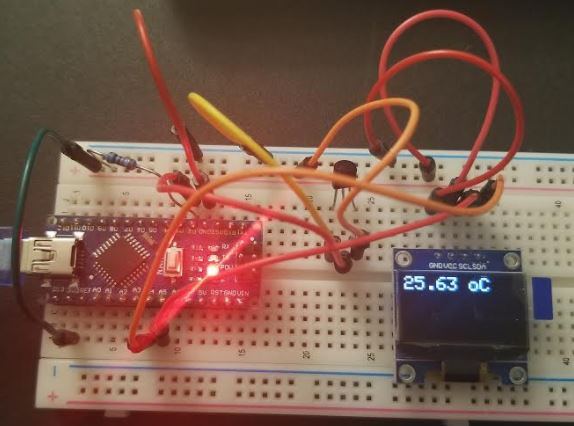
However, you can see that it
is not perfect, the temperature degree
symbol has the 'o' as the subscription but not superscription. If you
would like to explore how to move it up as the superscription, go for
it.
Task
1.3: Repeat this
example on your side. (5 points)
2. Use
an ISR while displaying on ssd1306
In this project, the OLED
talks to the NANO through I2C, DS18b20 talks to the NANO through
OneWire, ESP8266 talks to the NANO using software UART. The libraries
we are using may have occupied the one of the Timers in the NANO. If we
would like to use interrupt to put the display function inside the ISR,
it may not work.
The best way to know this is
to test this out. I have a very simple ISR conflict testing function
you can use.
The first one is to test if
the ssd1306 display has any conflict with the Timer1's interrupt. The
sketch is here.
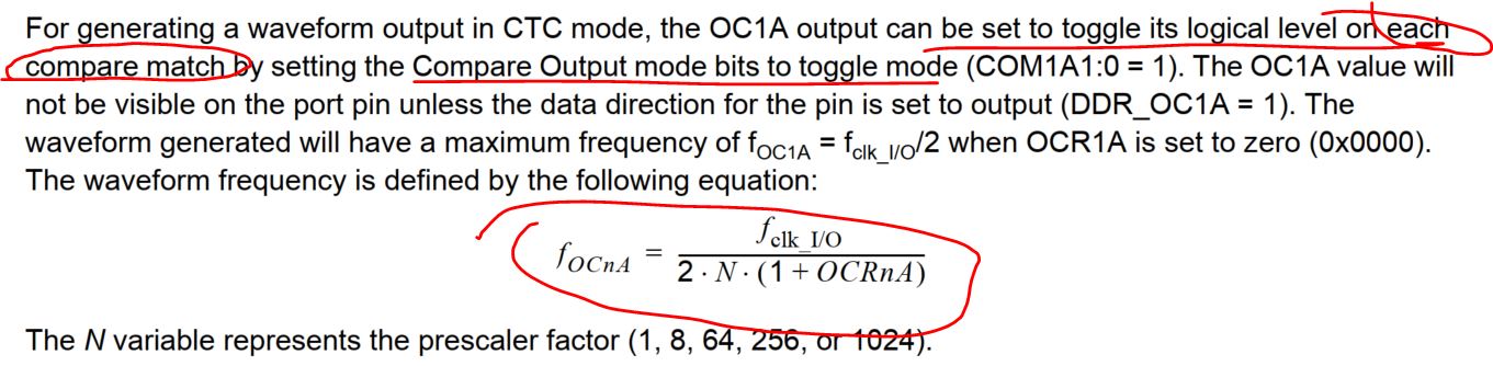
The OCR1A=62500 will allow
the LED to blink every 4 seconds. From the datasheet:
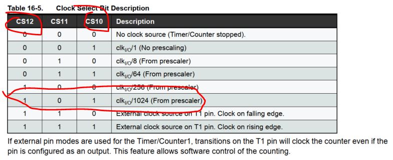
The prescaler factor, N, is
1024 in this example because:
Therefore, 1/T =
16M/(2x1024x62501)=0.125 Hz, so T=8s, which is period, and the ISR is
being triggered whenever it is toggled, so ISR is triggered every 4s.
This sketch will blink the
blue LED every 4s while keep the OLED display in realtime. Use your
finger to warm up the sensor to see if you can have realtime
temperature changes on the display. If this works, the interrupt ISR
and the display code have no Timer conflict.
After a few other tests, the Adafruit's ssd1306 display() function is
not compatible with the ESP8266's code.
Task 2: Repeat this
example on your side. (15 points)
3. The 2-NANO system with the ESP8266
3.1 Introduction to
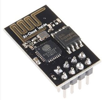
the ESP8266 WiFi module.
Caution!!!
Always use 3.3V
to power up your ESP8266. 5V will burn it!!!
Do not use the
3.3V voltage output pin from
the Arduino board to power up your ESP8266!! The 3.3V from Arduino can
only handle 40 mA as the maximum, ESP8266 will draw 200 - 600 mA during
operation!! Use a dedicated DC-DC regulator to power up the ESP8266 and
your NANO.
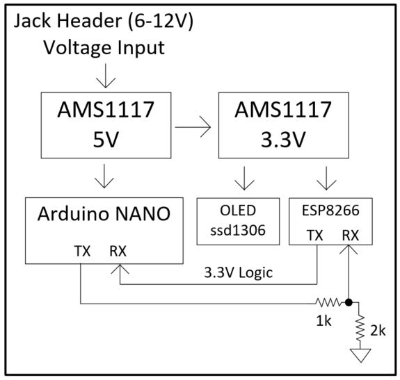
In your PCB design use both
AMS1117 5V and AMS1117 3.3V on your PCB:
The ESP8266 is a low-cost Wi-Fi microchip, with a full TCP/IP stack and
microcontroller capability, produced by Espressif Systems in Shanghai,
China. The chip first came to the attention of Western makers in August
2014 with the ESP-01 module, made by a third-party manufacturer
Ai-Thinker. This small module allows microcontrollers to connect to a
Wi-Fi network and make simple TCP/IP connections using Hayes-style
commands. However, at first there was almost no English-language
documentation on the chip and the commands it accepted. The very low
price and the fact that there were very few external components on the
module, which suggested that it could eventually be very inexpensive in
volume, attracted many hackers to explore the module, the chip, and the
software on it, as well as to translate the Chinese documentation. The
ESP8285 is an ESP8266 with 1 MB of built-in flash, allowing the
building of single-chip devices capable of connecting to Wi-Fi. The
successor to these microcontroller chips is the ESP32, released in
2016. (From Wikipedia)
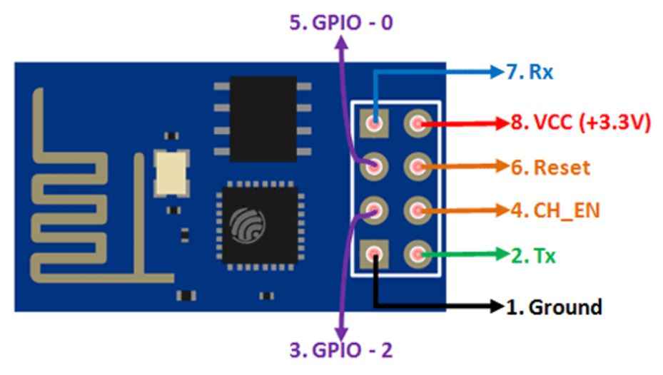
ESP8266
The pinout of ESP8266:
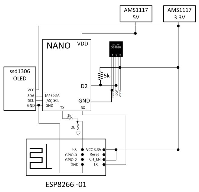
Make the following hardware
connections:
3.2 Build the IoT based temperature monitor
It turns out that the interrupt confict beteween the ssd1306's
display() function and the Serial.println() function (both hardware and
software) are not compatible. Which means as long as you are sending
data to ESP (UART is the only available port), there will be a
conflict. However, we do need the OLED to display a value locally.
Without changing the display strategy and digging into the libraries to
customize the libraries, we may need two NANOs to split the display and
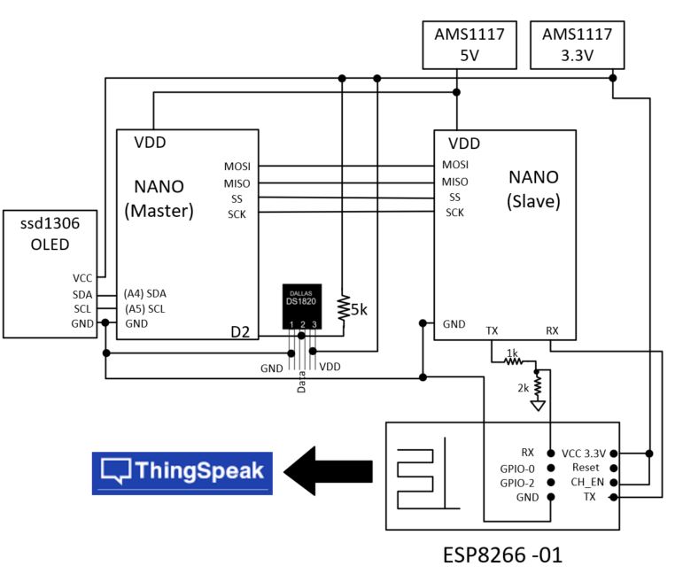
data transmission tasks.
The system diagram looks like this:
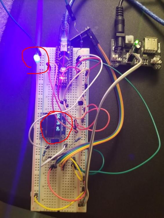
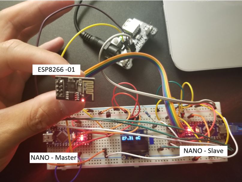
The connections on the board looks like this:
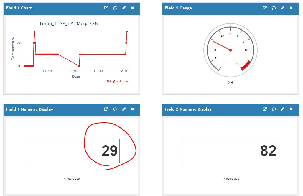
The data on ThingSpeak:
The sketch you can use to repeat this
work. Download the sketch for the master and the slave respectively.
The demonstration video:
Task 3: Repeat this
example on your side. (50 points)
4. Customizable WiFi credentials challenge
Task 4: Add a pushbutton or a few pushbuttons to the system to allow the user to change the WiFi AP username and password. (10 points) Task 5: Design the schematic and the PCB layout of the system in Eagle. (10 points)