Goals:
1. Be able to use LCD as the display device
2. Be able to use temperature, humidity, untrasonic, and remote sensors
3. Be able to use motors as actuators
1. The LCD (Liquid Crystal Display)
A liquid-crystal display (LCD) is a flat-panel display or other electronically modulated optical device that uses the light-modulating properties of liquid crystals. Liquid crystals do not emit light directly, instead using a backlight or reflector to produce images in color or monochrome.
A Casio Alarm Chrono digital watch with LCD.
To understand how LCD works by searching and reading articles online may be overwhelming. However, I found a fatastic video from SparkFun that explains how this works using a very simple and professional way (use a earphone if you are watching it in public):
In this section, you will learn how to wire up and use an alphanumeric LCD display. The display has an LED backlight and can display two rows with up to 16 characters on each row. You can see the rectangles for each character on the display and the pixels tht make up each character.
The LCD we'll use for this experiment is LCD1602: (datasheet)
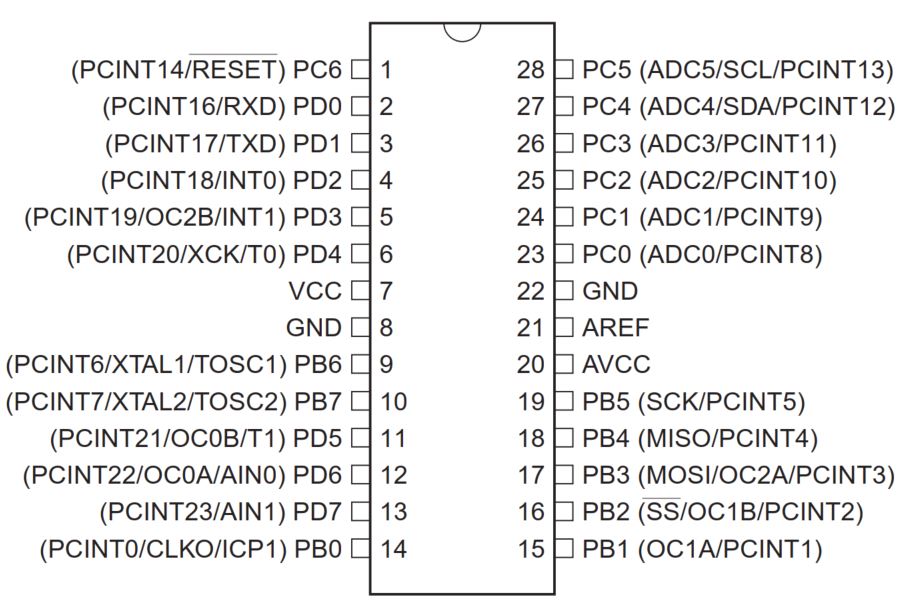
Pin names and functions:
VSS: A pin connects to groud.
VDD: A pin connects to +5V power supply on board.
VO: A pin adjusts the contrast of LCD1602.
RS: A register select pin controls where in the LCD's memory is being written. You can select either the data register, which holds what being displayed, or an instruction registerr, which is where the LCD's controller looks for instructions on what to do next.
R/W: A Read/Write pin selects the reading mode or the writting mode.
E: An enabling pin when being applied with low-level energy then triggers relevant instructions.
D0-D7: Pins write and read data.
A and K: Pins control the LED backlight.
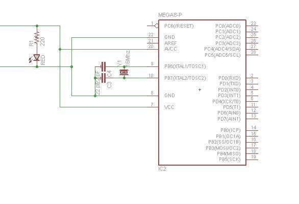
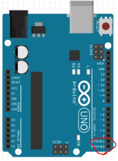
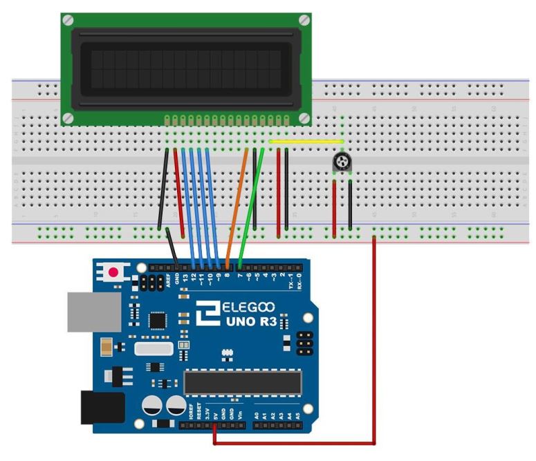
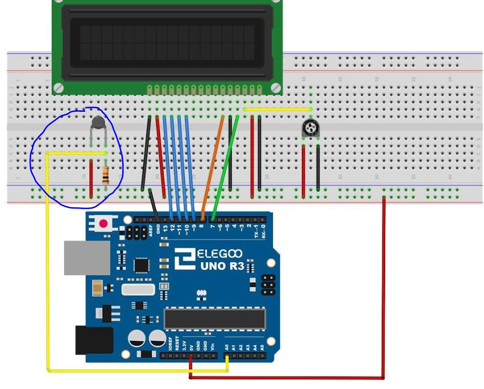
Follow the connections in the figure below to wire up your boards:
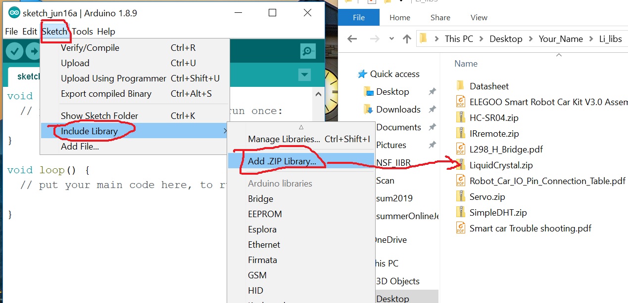
Before you start typing your code into the Arduino IDE, download and add the 'zip' library to your IDE.
Open the Arduino IDE, go to Sketch - Include Library - Add Zip Library - Find the location of the 'LiquidCrystal.zip' library, then add it to the IDE.
Then you are ready to go:
Use the following example code to get your first 'Hellow World!' on your LCD:
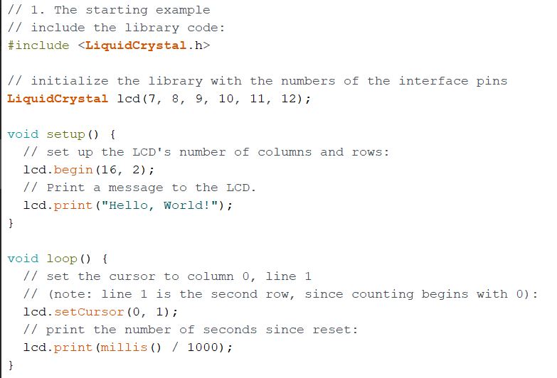
In which,
lcd.print(millis() / 1000) does integer division. Counts by one for every 1000 miliseconds
lcd.setCursor(0,1) defines the starting position (column 0 & row 1) to display the data . Both column and row numbers start at 0 rather than 1.
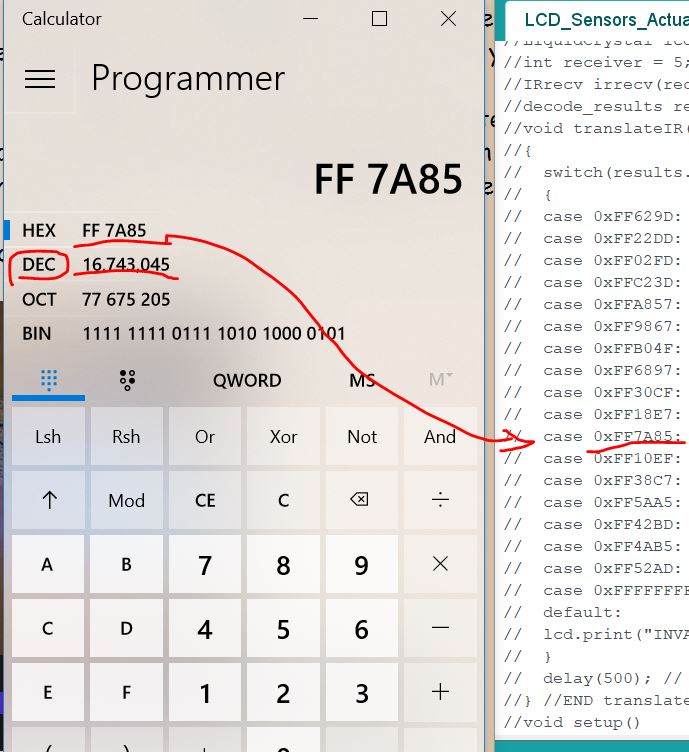
You should see this on your side:
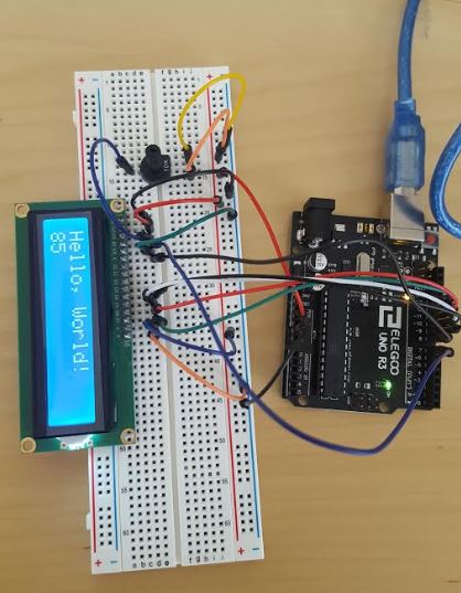
Please note that it does not have to be '85' on the second line. Mine was just counted to 85. It will start from 0 and count up.
Task 1: Display the 'Hello World!' starting from the second rectangle on the same line.
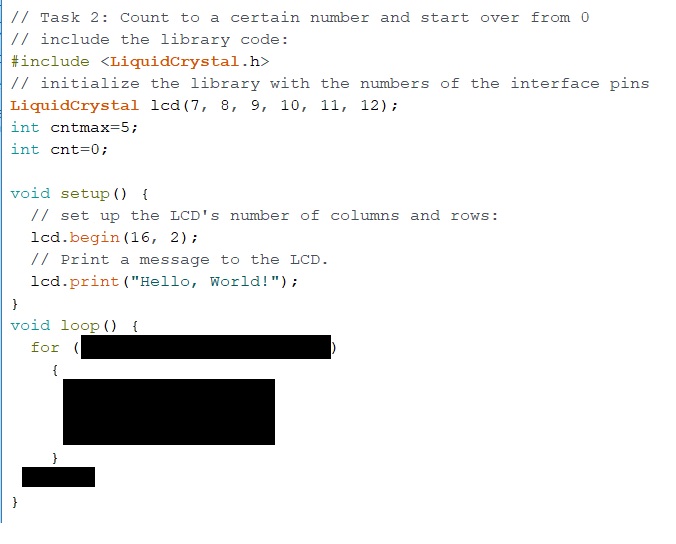
Task 2: Count to 5 and then reset to 0, then start over:
Some hints for Task 2:
Task 3: Given that the command 'lcd.clear()' will clear out everything on the LCD. Modify the code to implement the scrolling text as presented in the video below:
The 'Liquid Crystal' library loaded to the Arduino IDE in the beginning has made this entire programming process much less stressful so the developer can focus on the software and the control strategy other than focusing on the hardware. Back to 10 years ago when I was in college, there were not too much resource like this for developers. It was more challenging for beginners to have fun with these MCUs.
2. Sensors
2.1 Temperature and Humidity Sensors
2.1.1 Use a Thermistor to mesure the temperature
A thermistor is a thermal resistor - a resistor changes its resistance with temperature. Technically, all resistors are thermistors - their resistance changes slightly with temperature - but the change is usually very small and difficult to measure. Thermistors are made so that the resistance changes drastically with temperature so that it can be 100 ohms or more of change per degree.
There are two kinds of thermistors, NTC (negative temperature coefficient) and PTC (positive temperature coefficient). In general you will see NTC sensors used for temperature measurement (we'll used NTC in this experiment). PTC's are often used as resettable fuses - an increase in temperature increases the resistance which means as more current passes through them, they heat up and 'choke back' the current, quite handy for protecting circuits!
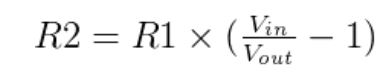
Since the thermistor is a variable resistor, we’ll need to measure the resistance before we can calculate the temperature. However, the Arduino can’t measure resistance directly, it can only measure voltage. The Arduino will measure the voltage at a point between the thermistor and a known resistor. This is known as a voltage divider. The equation for a voltage divider is:
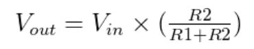
This equation can be rearranged and simplified to solve for R2, the resistance of the thermistor:
Finally, the Steinhart-Hart equation is used to convert the resistance of the thermistor to a temperature reading.
The Thermistor looks like this:
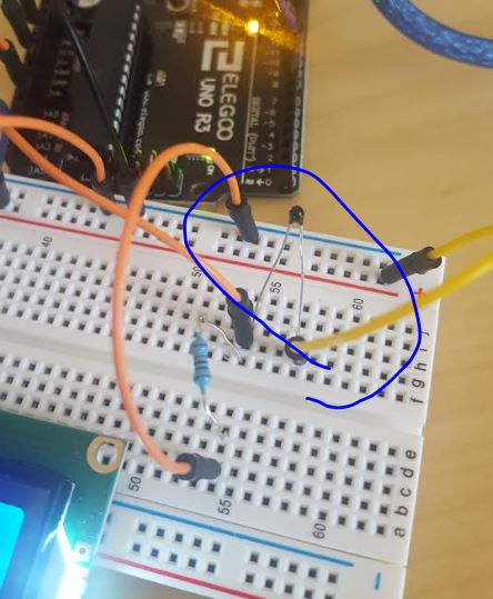
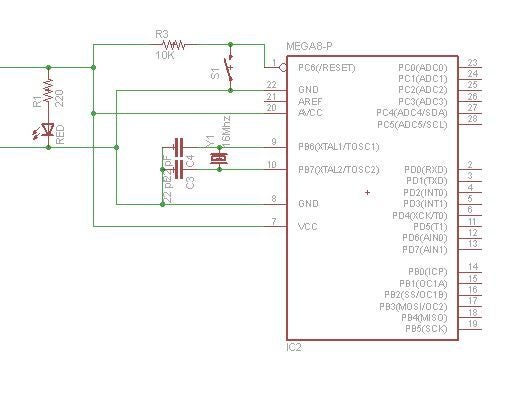
Add the Thermistor and a 10K resistor to the existing circuit:
The Steinhart–Hart equation: (Just for your reference, you do not need to remember this equation)
The Steinhart–Hart equation is a model of the resistance of a semiconductor at different temperatures. The equation is
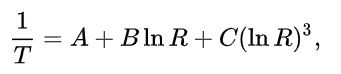
T is the temperature (in kelvins),
R is the resistance at T (in ohms),
A, B, and C are the Steinhart–Hart coefficients, which vary depending on the type and model of thermistor and the temperature range of interest. (The most general form of the applied equation contains a (lnR)^2 term, but this is frequently neglected because it is typically much smaller than the other coefficients, and is therefore not shown above.)
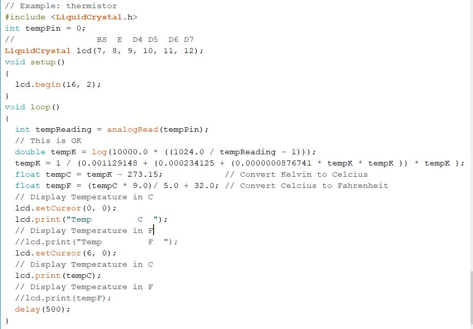
Use the following example code to convert resistance changes to tempterature changes.
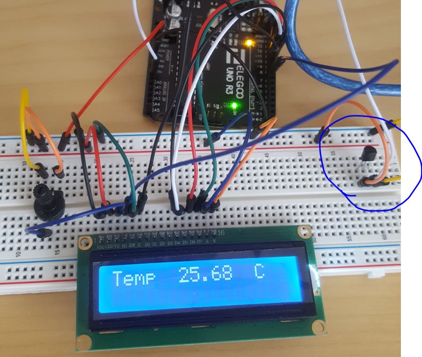
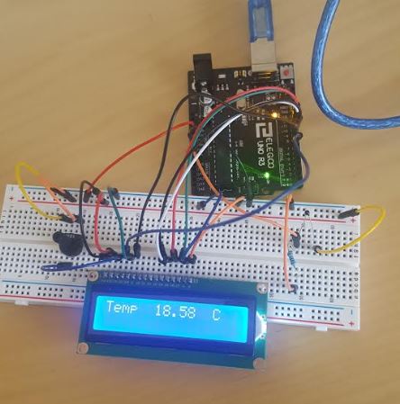
The result looks like the following:
Task 4: Repeat the work above, show room temperature on the LCD. Use your finger to warm it up see if it changes.
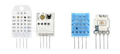
2.1.2 Use DHT11 to measure temperature and humidity
DHT11 temperature and humidity sensor is good enough for most projects that need to keep track of humidity and temperature readings. Load the library to your Arduino IDE. The 'SimpleDHT.zip' library.
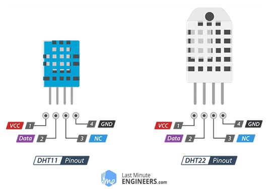
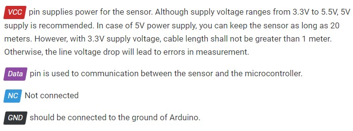
The sensor's pins:
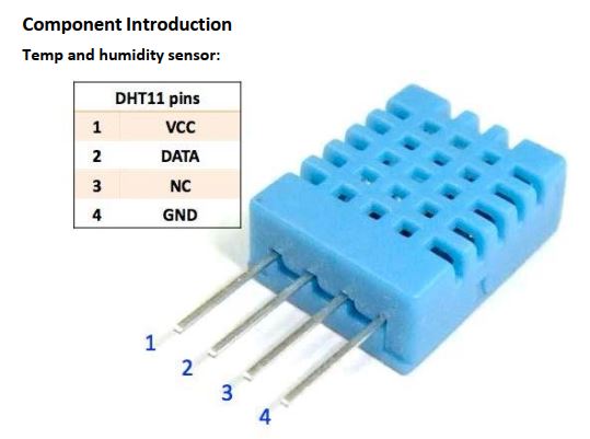
There is a newer version (DHT12, white, which is not being used in this tutorial).
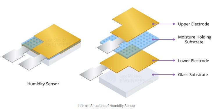
Humidity sensing component is used, of course to measure humidity, which has two electrodes with moisture holding substrate (usually a salt or conductive plastic polymer) sandwiched between them. The ions are released by the substrate as water vapor is absorbed by it, which in turn increases the conductivity between the electrodes. The change in resistance between the two electrodes is proportional to the relative humidity. Higher relative humidity decreases the resistance between the electrodes, while lower relative humidity increases the resistance between the electrodes.
The DHT sensor has been mounted to a PCB in your Arduino Kit so plesae directly use that one for your experiment.
DHT11 digital temperature and humidity sensor is a composite sensor which contains a calibrated digital signal output of the temperature and humidity. The sensor includes a resistive sense of wet components and a NTC temperature measurement devices, and connects with a high-performance 8-bit microcontroller.
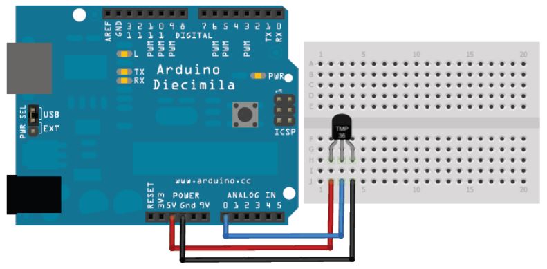
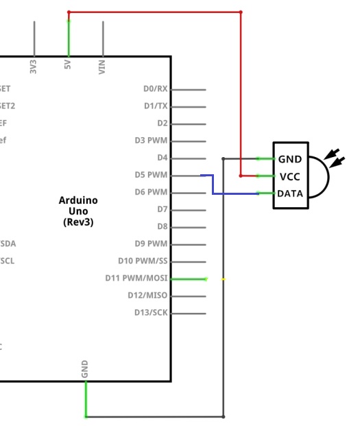
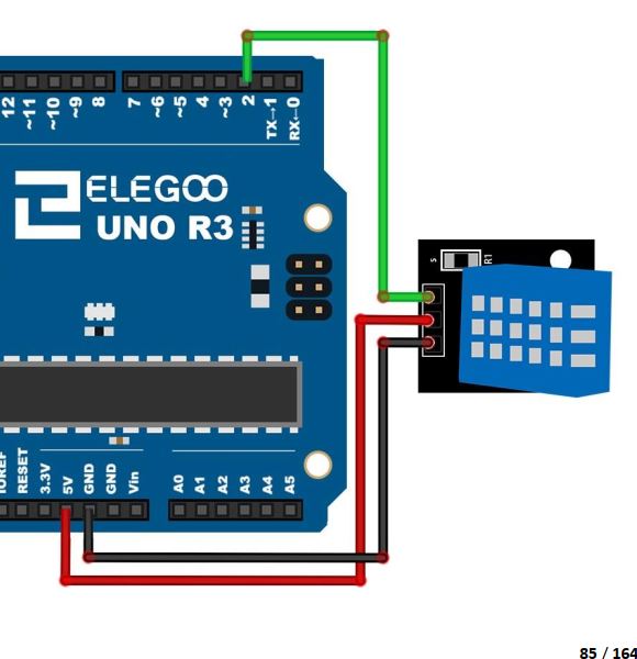
Please add the following connections to your existing connections in the LCD sections.
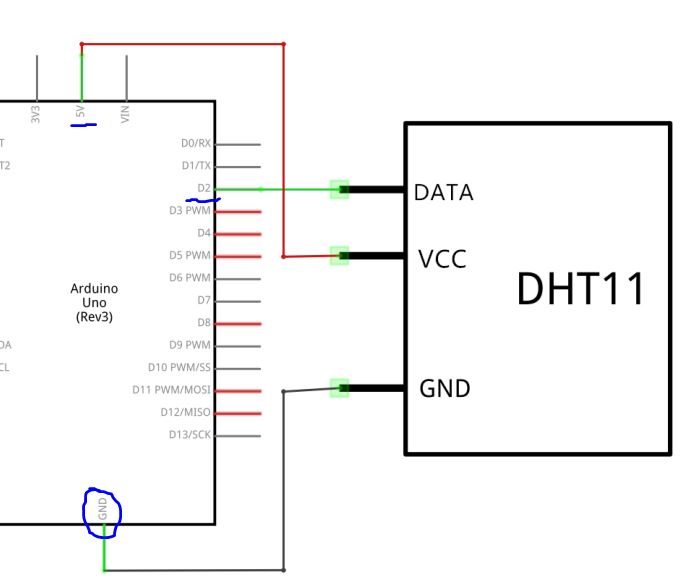
It looks as follows on the board:
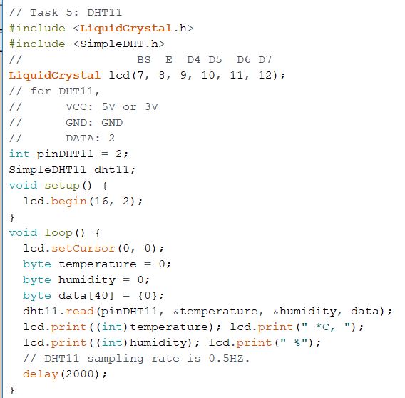
The example code:
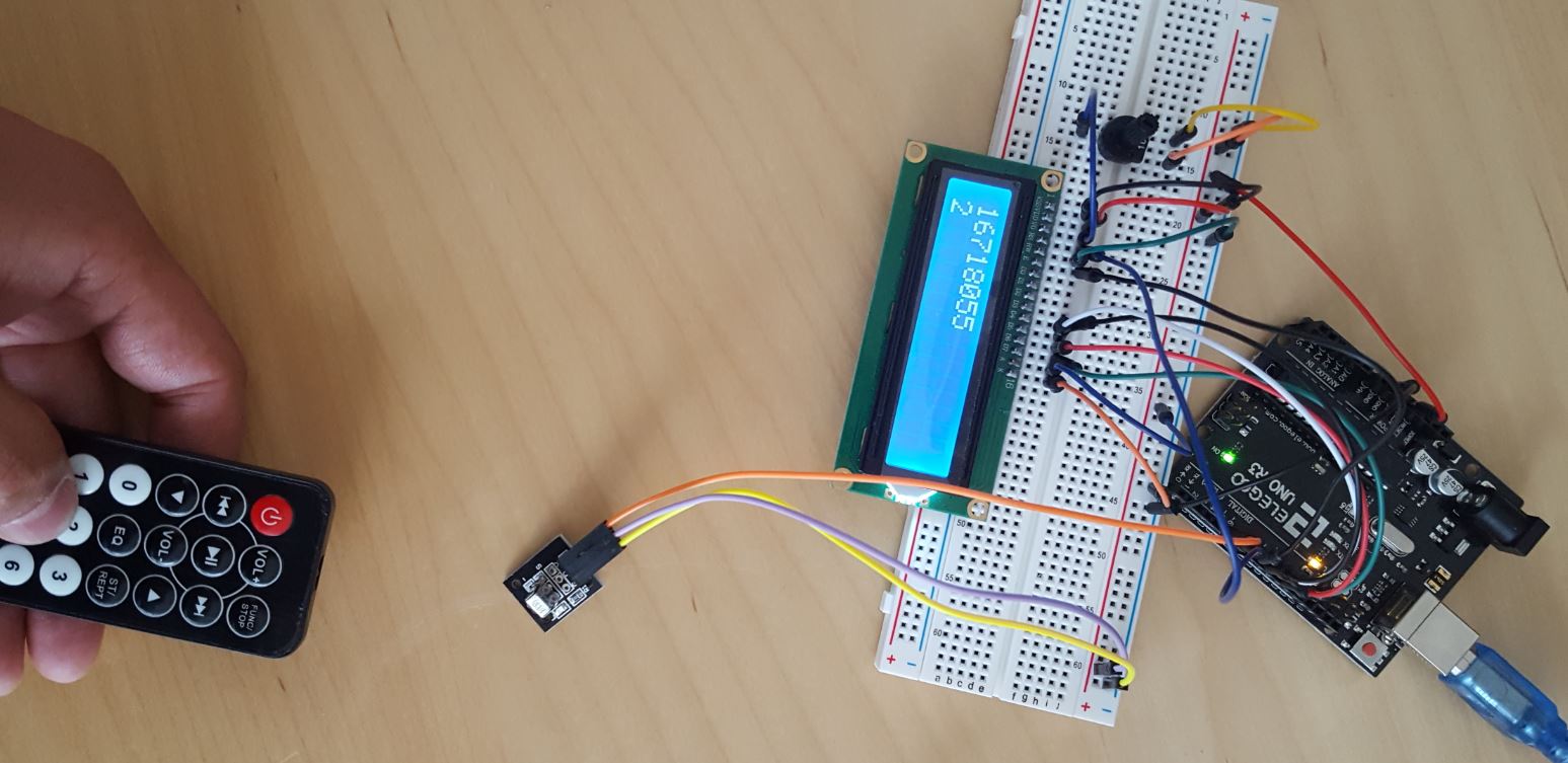
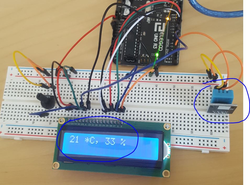
The results on my side:
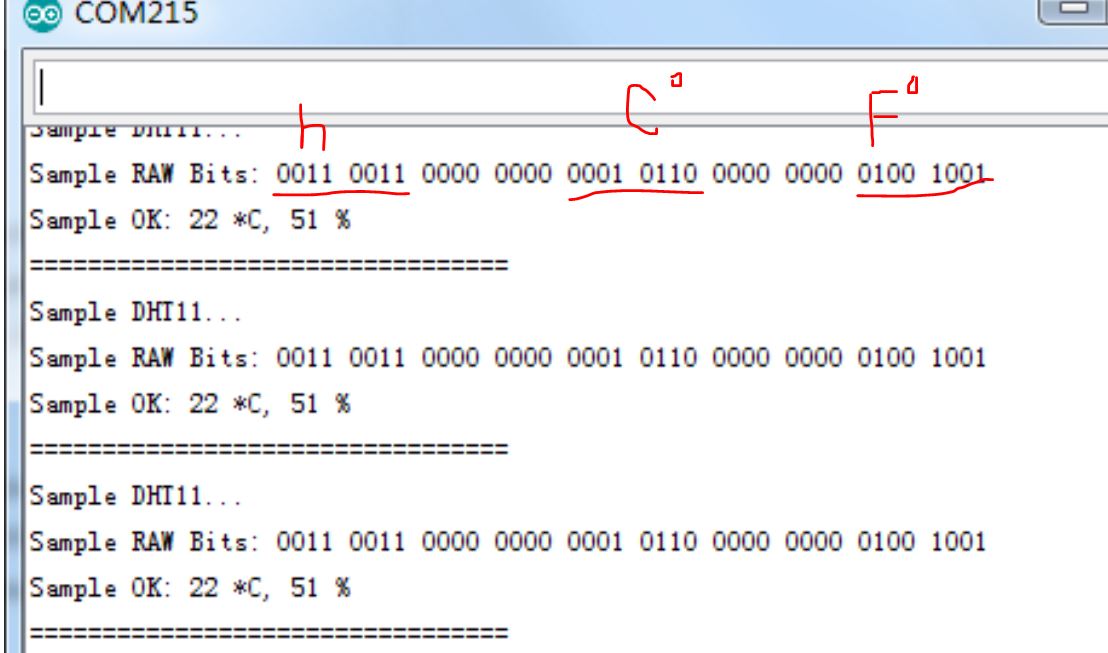
To understand how the 'dht11.read()' function works, run the following example:
Code and results:
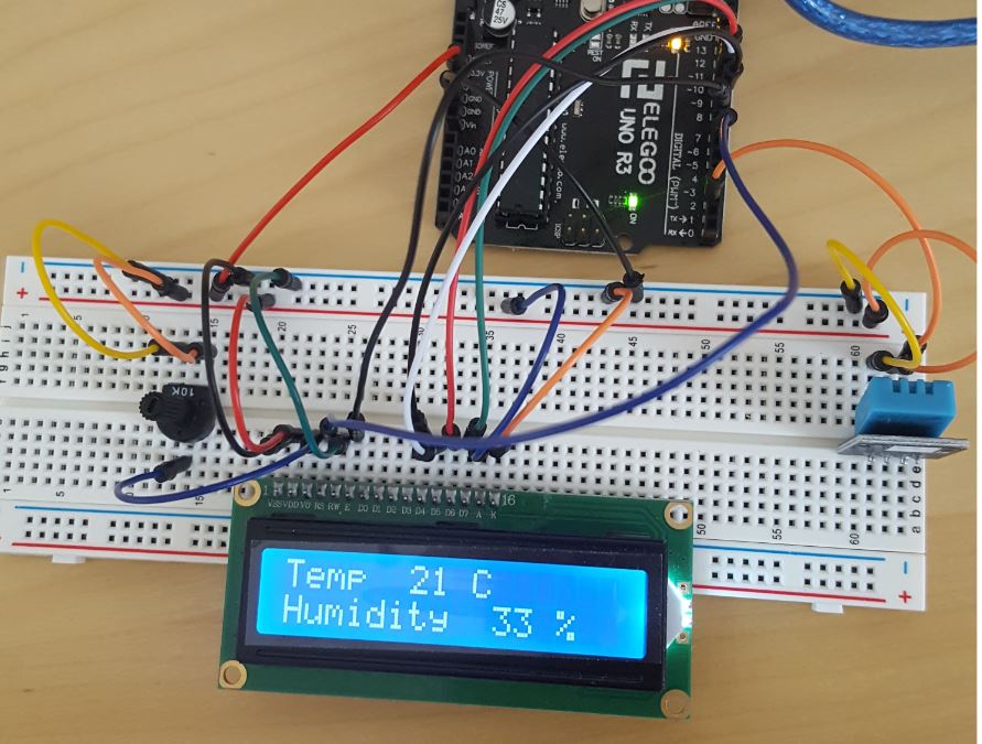
Task 5: Modify the code to display in the form below. Simply blow at the sensor to change the temperature and the humidity to test it. Show a demonstration video in your report.
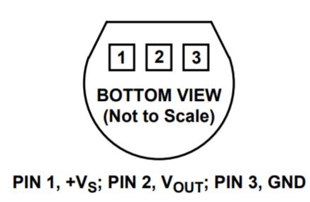
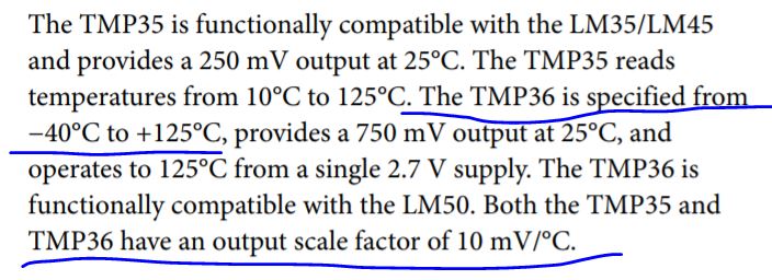
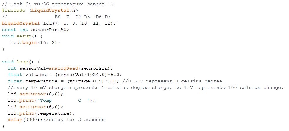
2.1.3 Use an integrated circuit temperature sensor
In this section, we will use an electronic integrated circuit temperature sensor. The Vendor is Analog Devices. There are only three pins out of the sensor. VDD, VSS, and analog output. The analog output voltage change carries the information of the temperature change in the environment. A snapshot from the datasheet of the sensor: