ESP32
WiFi-BT-BLE MCU Module / ESP-WROOM-32
Task 1 - Task 8: 10 points for each
Task 9: 20 points.
An brief introduction of the
module can be found at Adafruit's website:
https://www.adafruit.com/product/3320
The PCB evaluation board is
from HiLetgo.
The
schematic comes with the evaluation boad (PDF)
1. Setup
and the first example.
1.1. Install the library and basic configurations
One way to install it is through the Board Manager. However, you will need to load the website to Preference first:
Go to File - Prefernece. Add this line to the address box:
https://dl.espressif.com/dl/package_esp32_index.json, http://arduino.esp8266.com/stable/package_esp8266com_index.json
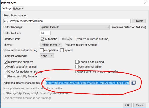
Then install it from the Board Manager:
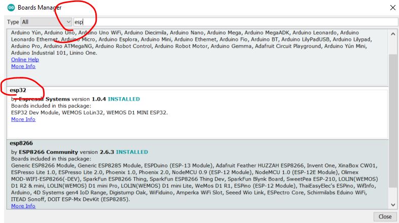
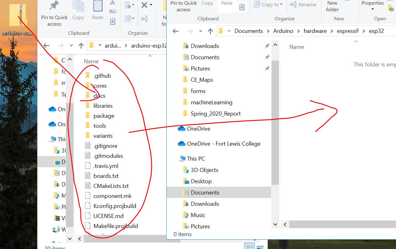
An alternative way to install it is through GitHub:
https://github.com/espressif/arduino-esp32
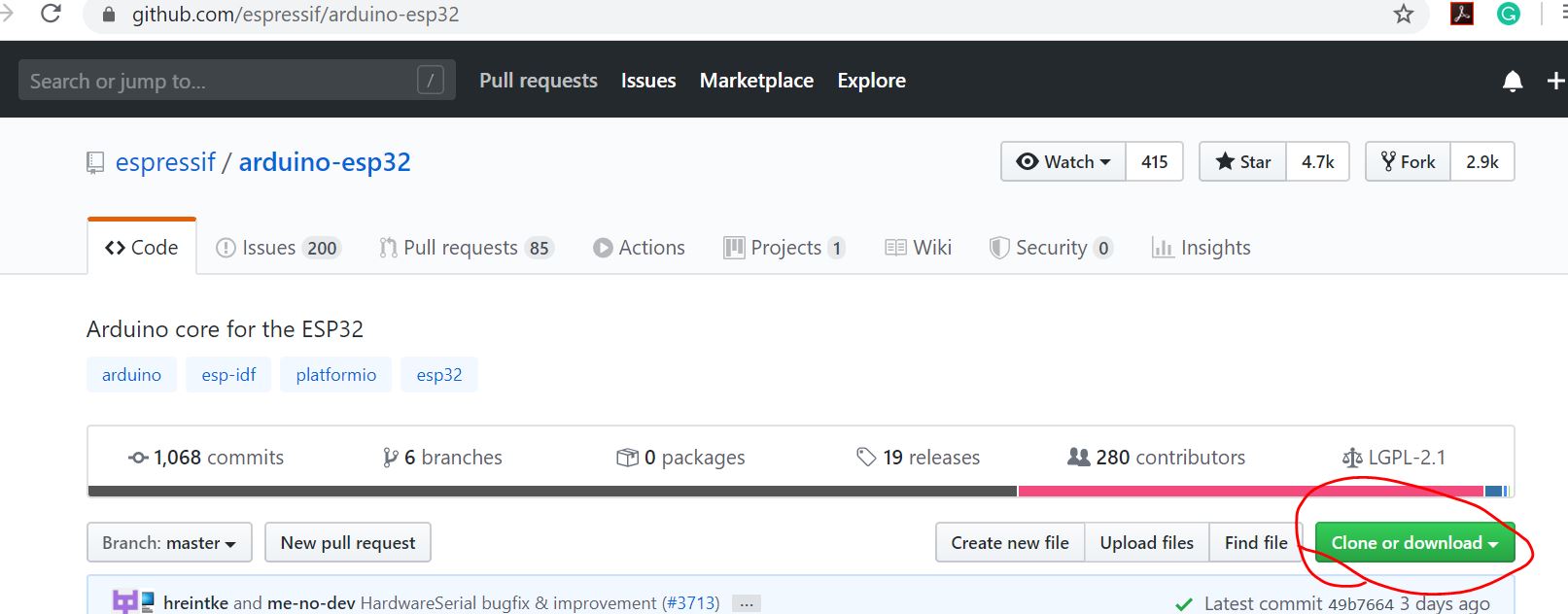
Extract the files and create a
folder in your local drive. Transfer the extracted files to the new
folder:
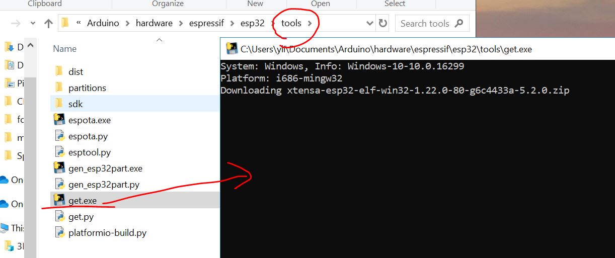
Double click the get.exe file
in 'tools':
1.2 Run the first example
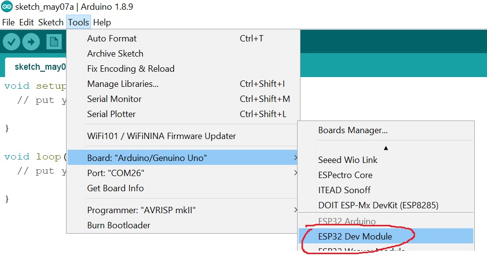
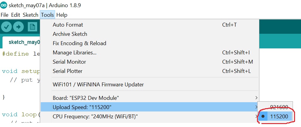
Open the Arduino IDE and
choose the 'ESP32 Dev Module' board, the '11520 upload speed', the
'AVRISP mkII' programmer, and the correct port:
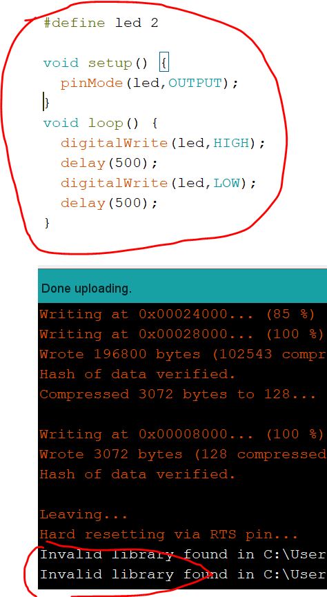
Code up a very simple
blinking program and upload it to the board. Keep in mind you must hold
the Boot button on the board when you see 'connecting
..........._______' until it starts upload the code.
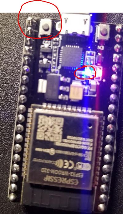
The highlighted push button in the following figure is the
'Boot' button. After the code is uploaded to the board, the LED on the board will blink.
Task 1: Repeat the work above and show the results in a Video in your lab report.
2.
Communicate with MPU6050 - a 16 bit Accelerometer and Gyroscope.
A good website for ESP examples. https://randomnerdtutorials.com/esp32-i2c-communication-arduino-ide/
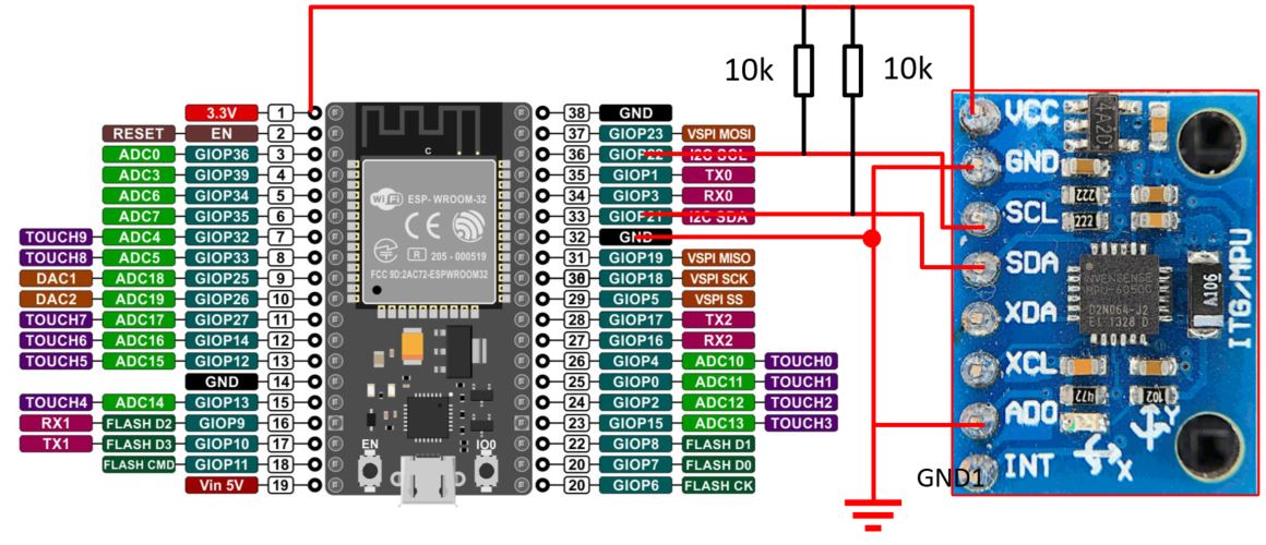
The ESP 32 module has I2C ports available. Make the following hardware
connections. Don't forget to pull the SCL and SDA pins to VCC using two
pull-up resistors (10k here).
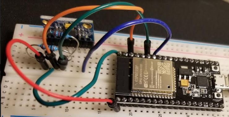
The circuit on a breadboard:
In the following code, compared to the one I used in a different tutorial in CE 315 (http://yilectronics.com/Courses/CE315/CE315_2020s/lectures/Tutorial_6_I2C_Accelerometer/I2C_SPI.html),
the AccX, AccY, and AccZ here must be 'int16_t'. The CE 315 tutorial
is based on an 8-bit computer chip ATMega 328p. However, ESP32 is a
32-bit computer chip, you need to define a specific signed 16bit
variable to hold the 16-bit acceleration data. Ideally, this shouldn't
be a problem but it does happen to ESP32. This problem may be solved by
their engineers in the future versions of ESP32.
After upload the code to the
ESP board, you must unplug and plug the USB cable back in before you
turn on the Serial Plotter.
Task 2: Repeat the work above and show the results in a Video on your lab report.
* A very practical and important note:
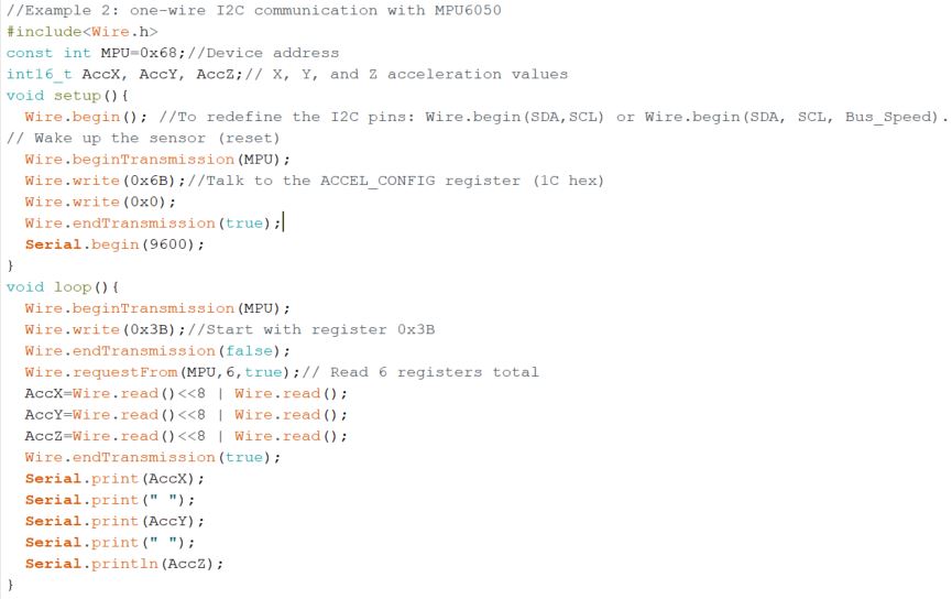
In the code example
above, AccX, AccY, and AccZ are defined as int16_t and the results are
binary numbers. It is fine to keep the binary version and not convert
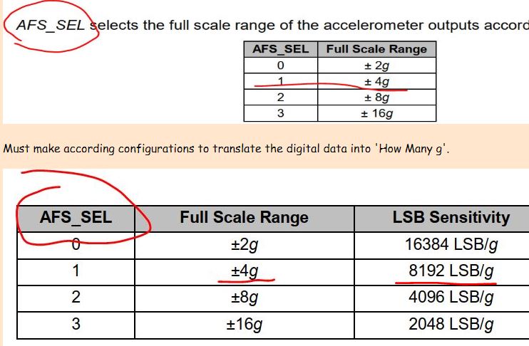
them to g's to save computation time (avoid division operation). You can definitely convert these numbers into g's by dividing a
pre-determined factor (refer to the register Map PDF). Here, the range is 4g so you need to divide the
results by 8192. If you do not set up the AFS_SEL register, the default
value should be 0 and the factor to divide is 16384 LSB/g and the range
is +-2g.
Now, let's try some options to see what the results look like:
Code 1: This is the code that may come to your mind at the first time. This will work in your Arduino chip but not here.
-----------------------------------------
//test variable types and division factors
#include<Wire.h>
const int MPU=0x68;//Device address
float AccX, AccY, AccZ;
void setup(){
Wire.begin(); //To redefine the I2C pins: Wire.begin(SDA,SCL) or Wire.begin(SDA, SCL, Bus_Speed).
// Wake up the sensor (reset)
Wire.beginTransmission(MPU);
Wire.write(0x6B);
Wire.write(0x00);
Wire.endTransmission(true);
Wire.beginTransmission(MPU);//Talk to the ACCEL_CONFIG register (1C hex)
Wire.write(0x1C);
Wire.write(0x08);//Set the register bits as 00001000 (+/- 4g full scale range)
Wire.endTransmission(true);
Serial.begin(9600);
}
void loop(){
Wire.beginTransmission(MPU);
Wire.write(0x3B);//Start with register 0x3B
Wire.endTransmission(false);
Wire.requestFrom(MPU,6,true);// Read 6 registers total
AccX=(Wire.read()<<8 | Wire.read())/8192.0;
AccY=(Wire.read()<<8 | Wire.read())/8192.0;
AccZ=(Wire.read()<<8 | Wire.read())/8192.0;
Wire.endTransmission(true);
Serial.print(AccX);
Serial.print(" ");
Serial.print(AccY);
Serial.print(" ");
Serial.println(AccZ);
}
-----------------------------------------
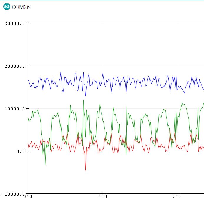
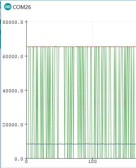
Let's look at the results.
Apparently they are incorrect. The minimum values are 0's but we know that the acceleration
values can be negative values. Something is wrong. It seems that the
signed numbers are being treated as unsigned numbers. Weird.
Code 2: Now, let's get rid of the divisions and just keep the binary numbers but still keep the data type as float.
-----------------------------------------
//test variable types and division factors
#include<Wire.h>
const int MPU=0x68;//Device address
float AccX, AccY, AccZ;
void setup(){
Wire.begin(); //To redefine the I2C pins: Wire.begin(SDA,SCL) or Wire.begin(SDA, SCL, Bus_Speed).
// Wake up the sensor (reset)
Wire.beginTransmission(MPU);
Wire.write(0x6B);
Wire.write(0x00);
Wire.endTransmission(true);
Wire.beginTransmission(MPU);//Talk to the ACCEL_CONFIG register (1C hex)
Wire.write(0x1C);
Wire.write(0x08);//Set the register bits as 00001000 (+/- 4g full scale range)
Wire.endTransmission(true);
Serial.begin(9600);
}
void loop(){
Wire.beginTransmission(MPU);
Wire.write(0x3B);//Start with register 0x3B
Wire.endTransmission(false);
Wire.requestFrom(MPU,6,true);// Read 6 registers total
AccX=Wire.read()<<8 | Wire.read();
AccY=Wire.read()<<8 | Wire.read();
AccZ=Wire.read()<<8 | Wire.read();
Wire.endTransmission(true);
Serial.print(AccX);
Serial.print(" ");
Serial.print(AccY);
Serial.print(" ");
Serial.println(AccZ);
}
-----------------------------------------
The results:
It's not getting any better at all!
Code 3: Now let's change the data type back to int16_t but keep the division out of the code.
-----------------------------------------
//test variable types and division factors
#include<Wire.h>
const int MPU=0x68;//Device address
int16_t AccX, AccY, AccZ;
void setup(){
Wire.begin(); //To redefine the I2C pins: Wire.begin(SDA,SCL) or Wire.begin(SDA, SCL, Bus_Speed).
// Wake up the sensor (reset)
Wire.beginTransmission(MPU);
Wire.write(0x6B);
Wire.write(0x00);
Wire.endTransmission(true);
Wire.beginTransmission(MPU);//Talk to the ACCEL_CONFIG register (1C hex)
Wire.write(0x1C);
Wire.write(0x08);//Set the register bits as 00001000 (+/- 4g full scale range)
Wire.endTransmission(true);
Serial.begin(9600);
}
void loop(){
Wire.beginTransmission(MPU);
Wire.write(0x3B);//Start with register 0x3B
Wire.endTransmission(false);
Wire.requestFrom(MPU,6,true);// Read 6 registers total
AccX=Wire.read()<<8 | Wire.read();
AccY=Wire.read()<<8 | Wire.read();
AccZ=Wire.read()<<8 | Wire.read();
Wire.endTransmission(true);
Serial.print(AccX);
Serial.print(" ");
Serial.print(AccY);
Serial.print(" ");
Serial.println(AccZ);
}
-----------------------------------------
Results:
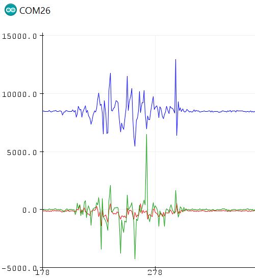
Now it works!
Code 4: Now let's add the division back to convert the data in the +- 4g range.
}
-----------------------------------------
//test variable types and division factors
#include<Wire.h>
const int MPU=0x68;//Device address
int16_t AccX, AccY, AccZ;
void setup(){
Wire.begin(); //To redefine the I2C pins: Wire.begin(SDA,SCL) or Wire.begin(SDA, SCL, Bus_Speed).
// Wake up the sensor (reset)
Wire.beginTransmission(MPU);
Wire.write(0x6B);
Wire.write(0x00);
Wire.endTransmission(true);
Wire.beginTransmission(MPU);//Talk to the ACCEL_CONFIG register (1C hex)
Wire.write(0x1C);
Wire.write(0x08);//Set the register bits as 00001000 (+/- 4g full scale range)
Wire.endTransmission(true);
Serial.begin(9600);
}
void loop(){
Wire.beginTransmission(MPU);
Wire.write(0x3B);//Start with register 0x3B
Wire.endTransmission(false);
Wire.requestFrom(MPU,6,true);// Read 6 registers total
AccX=(Wire.read()<<8 | Wire.read())/8192; // I use 8192 but not 8192.0 because AccX is an integer data type.
AccY=(Wire.read()<<8 | Wire.read())/8192;
AccZ=(Wire.read()<<8 | Wire.read())/8192;
Wire.endTransmission(true);
Serial.print(AccX);
Serial.print(" ");
Serial.print(AccY);
Serial.print(" ");
Serial.println(AccZ);
}
}
-----------------------------------------
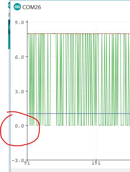
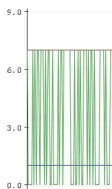
You can probably predict the
results. The code is not correct because the precision is not enough to
resolve all the variables. Imagine that if the data is 0.9g, it will be
treated as 0 in the integer division.
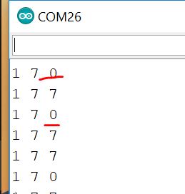
Look at the numbers.
Definitely the 0's are something not being resolved. However why '7' is
possible in the 4g range? I am not sure but since the code is not right
anyway there must be some glitches somewhere else.
Code 5: Now let's find a solution to this problem:
-----------------------------------------
//test variable types and division factors
#include<Wire.h>
const int MPU=0x68;//Device address
float AccX, AccY, AccZ;
int16_t AccX_temp, AccY_temp, AccZ_temp;
void setup(){
Wire.begin(); //To redefine the I2C pins: Wire.begin(SDA,SCL) or Wire.begin(SDA, SCL, Bus_Speed).
// Wake up the sensor (reset)
Wire.beginTransmission(MPU);
Wire.write(0x6B);
Wire.write(0x00);
Wire.endTransmission(true);
Wire.beginTransmission(MPU);//Talk to the ACCEL_CONFIG register (1C hex)
Wire.write(0x1C);
Wire.write(0x08);//Set the register bits as 00001000 (+/- 4g full scale range)
Wire.endTransmission(true);
Serial.begin(9600);
}
void loop(){
Wire.beginTransmission(MPU);
Wire.write(0x3B);//Start with register 0x3B
Wire.endTransmission(false);
Wire.requestFrom(MPU,6,true);// Read 6 registers total
AccX_temp=Wire.read()<<8 | Wire.read();
AccX=AccX_temp/8192.0;
AccY_temp=Wire.read()<<8 | Wire.read();
AccY=AccY_temp/8192.0;
AccZ_temp=Wire.read()<<8 | Wire.read();
AccZ=AccZ_temp/8192.0;
Wire.endTransmission(true);
Serial.print(AccX);
Serial.print(" ");
Serial.print(AccY);
Serial.print(" ");
Serial.println(AccZ);
}
-----------------------------------------
Results: It is just perfect.
Because the ESP32 is not able to handle the 16-bit MPU data pacakges
very well, we have to make the adjustments accordingly to make it work.
This is the only solution to this problem by far.
However, you are always
allowed or sometimes forced to get rid of the division operation in
order to save computation time in the realtime data collection.
Task 3: Read
the explanation in Code 1 - Code 5 above, repeat the work in Code 5,
show the demonstration video in your report.
3.
Communicate with an SD card through SPI
Explanation to SPI
SD card pin map:
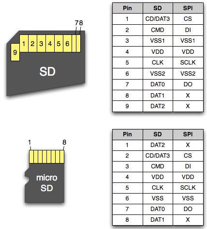
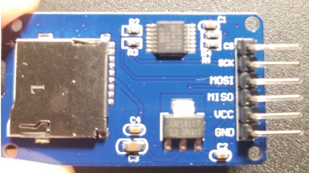
Using an micro SD card
adapter will make things easier
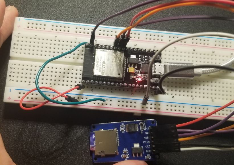
The connections between ESP32
and the SD card adapter is:
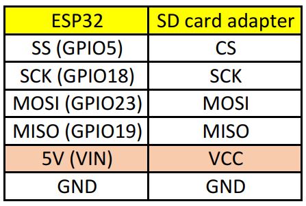
Pay special attention to the
5V-VCC connection. You must use 5V to power up the SD card adapter
because it has a 3.3V 'AMS1117' voltage regulater on the board. If you
directly use the 3.3 V voltage from the ESP board to power up the SD
card adapter, there will be a voltage loss through the AMS1117 chip and
causes insufficient volage supplied to the SD card.
Use this code to test the functionality of the
SD card quickly before moving forward.
If you see something like the following figure, your SD card is communicating with your ESP board successfully.
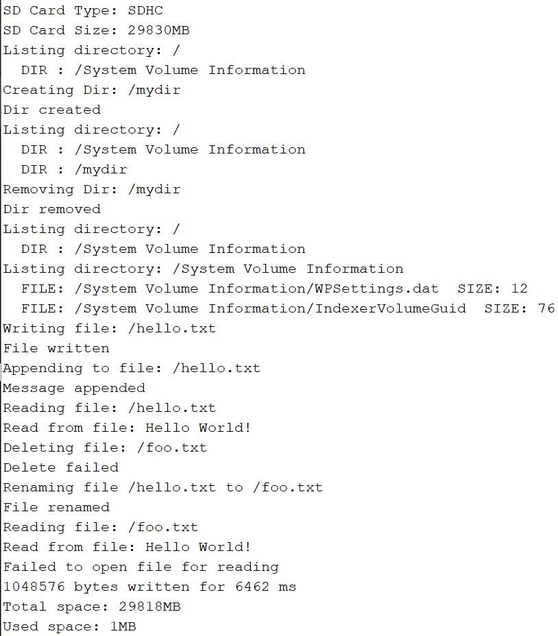
Task 4: Demonstrate the ESP communicates with the SD card, show results in your report.
4. Write the acceleration data to the SD card
Connect the MPU module back to the board.
Modify the code to write only the AccX data to the SD card.
In the following code, I
deleted most of the functions came with the SD card example code and
only kept the 'appendFile()' function. I duplicated the 'appendFile()'
function, renamed it as 'appendFile_char()'. These two functions append
'int16_t' data and 'const char' data to the file respectively.
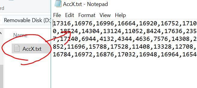
This code works pretty well. It'll generate a 'AccX.txt' file on the SD card. The data points are separated by commas.
//Example 3, SD card receive AccX data, works
#include "FS.h"
#include "SD.h"
#include "SPI.h"
#include<Wire.h>
const int MPU=0x68;//Device address
int16_t AccX, AccY, AccZ;// X, Y, and Z acceleration values
void setup(){
Wire.begin(); //To redefine the I2C pins: Wire.begin(SDA,SCL) or Wire.begin(SDA, SCL, Bus_Speed).
// Wake up the sensor (reset)
Wire.beginTransmission(MPU);
Wire.write(0x6B);//Talk to the ACCEL_CONFIG register (1C hex)
Wire.write(0x0);
Wire.endTransmission(true);
Serial.begin(115200);
if(!SD.begin()){
Serial.println("Card Mount Failed");
return;
}
}
void loop(){
uint8_t cardType = SD.cardType();
if(cardType == CARD_NONE){
Serial.println("No SD card attached");
return;
}
accRead();
appendFile(SD, "/AccX.txt", AccX);
appendFile_char(SD, "/AccX.txt", ",");
}
void accRead(){
Wire.beginTransmission(MPU);
Wire.write(0x3B);//Start with register 0x3B
Wire.endTransmission(false);
Wire.requestFrom(MPU,6,true);// Read 6 registers total
AccX=Wire.read()<<8 | Wire.read();
// AccY=Wire.read()<<8 | Wire.read();
// AccZ=Wire.read()<<8 | Wire.read();
Wire.endTransmission(true);
// Serial.print(AccX);
// Serial.print(" ");
// Serial.print(AccY);
// Serial.print(" ");
// Serial.println(AccZ);
}
void appendFile(fs::FS &fs, const char * path, int16_t message){ // changed the argument type to int16_t
File file = fs.open(path, FILE_APPEND);
if(!file){
Serial.println("Failed to open file for appending");
return;
}
if(file.print(message)){
Serial.println("Message appended");
} else {
Serial.println("Append failed");
}
file.close();
}
void
appendFile_char(fs::FS &fs, const char * path, const char *
message){ // added an 'appendFile_char' function to append ',' as data
separators
Serial.printf("Appending to file: %s\n", path);
File file = fs.open(path, FILE_APPEND);
if(!file){
Serial.println("Failed to open file for appending");
return;
}
if(file.print(message)){
Serial.println("Message appended");
} else {
Serial.println("Append failed");
}
file.close();
}
Test this code on your ESP.
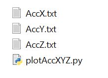
Task 5:
Modify the code to receive all AccX, AccY, and AccZ data in separate
data files 'AccX.txt', 'AccY.txt', and 'AccZ.txt'. Use Python to read
these three files and plot them in one figure (use Python is mandatory
for CE students). If you don't know Python, use MATLAB to plot them. (Refer to the Appendix of this tutorial for an example Python code).
Task 6:
Change the data type of AccX, AccY, and AccZ to 'float' and use
intermediate int16_t variables AccX_temp, AccY_temp, and AccZ_temp to
store the 16-bit accelleration data from the MPU sensor. TheAccX, AccY,
and AccZ data should be in the +- 4g range and being stored in the SD
card in three separate files. (similar to the technique used in Code 5 in Section 2 of this tutorial).
5. Communication between two ESP32 modules.
Use the following code only to check the MAC address of each device.
#include "WiFi.h"
void setup(){
Serial.begin(115200);
WiFi.mode(WIFI_MODE_STA);
Serial.println(WiFi.macAddress());
}
void loop(){
}
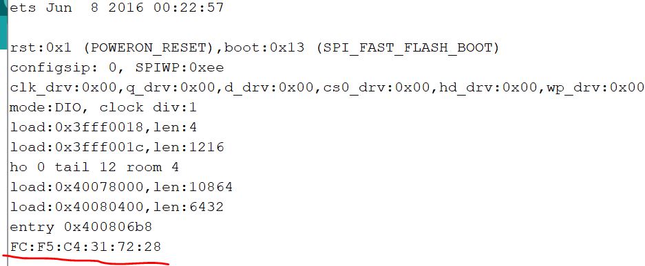
Open the serial monitor to check the MAC address. The following one
shows the MAC address of the slave device (connected to the SD card and
receives data from the ESP connected to the MPU sensor).(the slave receives data from the master)
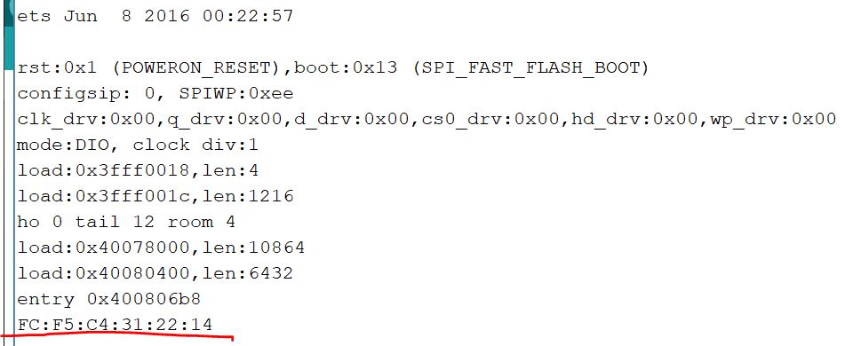
The MAC address of the master is also checked using the same method. (the master send data to the slave).
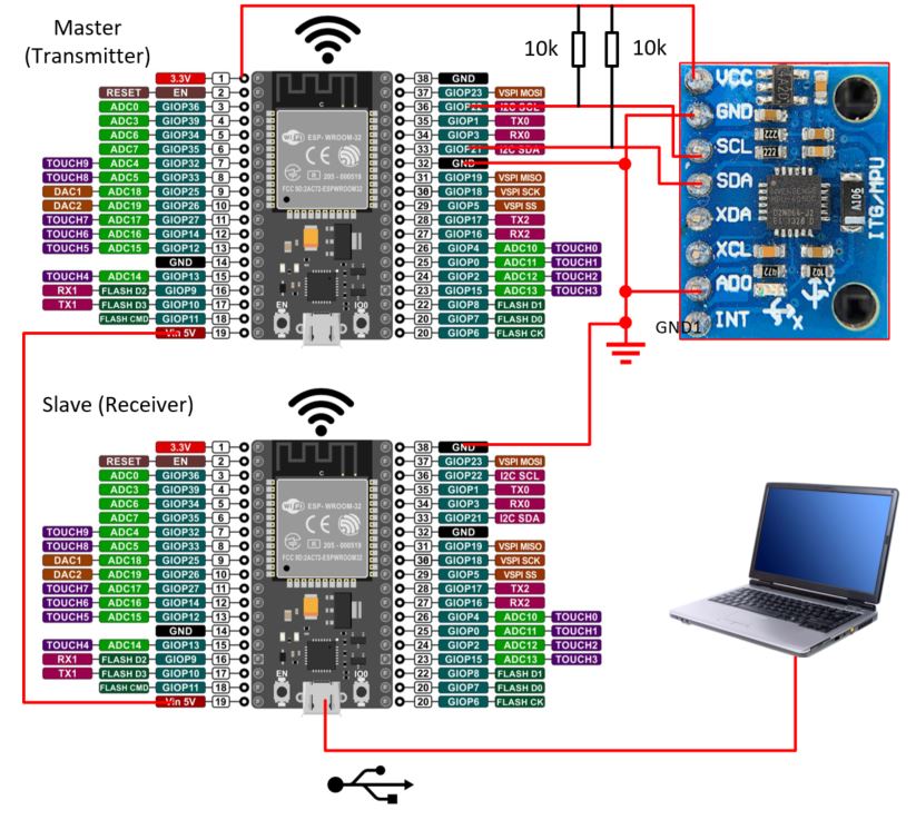
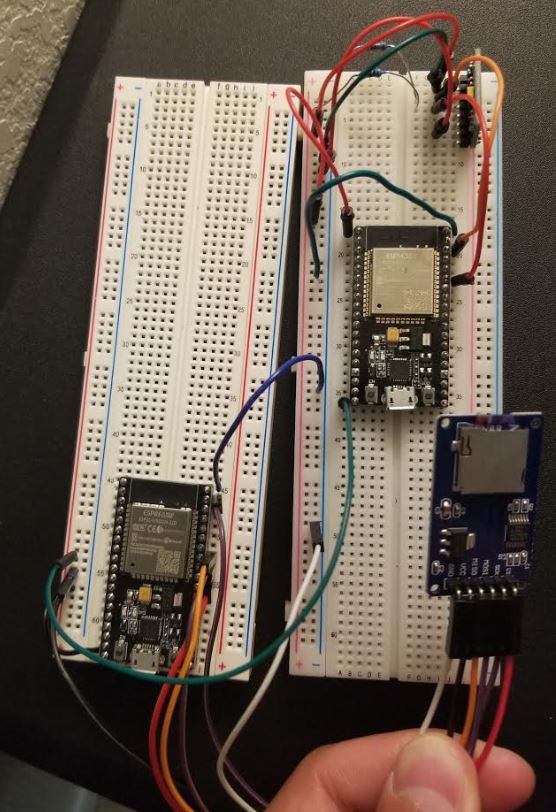
Connect the circuit as
follows. In this circuit, the master (transmitter) receives the
accelleration data through I2C and then relay the data to the slave
(receiver) through Bluetooth (the new ESP-Now IoT protocol), and
finally, the slave sends the data to a computer and plots the data in
the Arduino IDE serial plotter.
One important note,
keep the two EPS'5V voltage pins (pin 19) and the gnd of the two ESP boards
shortedrespectively. The only power source in this circuit is the 5V USB cable. The
ESP32 board has a AMS1117 voltage regulator which means the 3.3V on the
ESP board comes after the AMS1117. If you short the 3.3 V pins of the
two ESP boards, the one doesn't have the USB cable may be under powered
and will be mulfunctional.
The code for the master board.
-----------------------------------------
// Example 5_2, master, the ESP/accelerometer board, works
// Reference: https://randomnerdtutorials.com/esp-now-two-way-communication-esp32/
#include "FS.h"
#include "SD.h"
#include "SPI.h"
#include<esp_now.h>
#include<WiFi.h>
#include<Wire.h>
const int MPU=0x68;//Device address
float AccX, AccY, AccZ;
int16_t AccX_temp, AccY_temp, AccZ_temp;
String success;
uint8_t broadcastAddress[] = {0xFC, 0xF5, 0xC4, 0x31, 0x72, 0x28}; // Receiver's mac address
typedef struct struct_message{
float AccX;
float AccY;
float AccZ;
} struct_message;
struct_message MPU6050Readings;
void setup(){
Wire.begin(); //To redefine the I2C pins: Wire.begin(SDA,SCL) or Wire.begin(SDA, SCL, Bus_Speed).
// Wake up the sensor (reset)
Wire.beginTransmission(MPU);
Wire.write(0x6B);//Wake up the MPU chip
Wire.write(0x00);
Wire.endTransmission(true);
Wire.beginTransmission(MPU);
Wire.write(0x1C);//Talk to the ACCEL_CONFIG register (1C hex)
Wire.write(0x08);//Set the register bits as 00001000 (+/- 4g full scale range)
Wire.endTransmission(true);
Serial.begin(115200); // It's fine to use a higher speed other than
9600 but remember to change the rate in your serial monitor
WiFi.mode(WIFI_STA);
// Init ESP-NOW
if (esp_now_init() != ESP_OK) {
Serial.println("Error initializing ESP-NOW");
return;
}
// Once ESPNow is successfully Init, we will register for Send CB to get the status of Trasnmitted packet
// esp_now_register_send_cb(OnDataSent);
// Register peer
esp_now_peer_info_t peerInfo;
memcpy(peerInfo.peer_addr, broadcastAddress, 6);
peerInfo.channel = 0;
peerInfo.encrypt = false;
// Add peer
if (esp_now_add_peer(&peerInfo) != ESP_OK){
Serial.println("Failed to add peer");
return;
}
}
void loop(){
accRead();
MPU6050Readings.AccX=AccX;
MPU6050Readings.AccY=AccY;
MPU6050Readings.AccZ=AccZ;
esp_err_t
result = esp_now_send(broadcastAddress, (uint8_t *)
&MPU6050Readings, sizeof(MPU6050Readings)); //Send the data.
&MPU6050Readings is just a 8-bit character pointer to store the data
// if (result == ESP_OK) { // For debug purpose
// Serial.println("Sent with success");
// }
// else {
// Serial.println("Error sending the data");
// }
}
void accRead(){ // read the MPU data to ESP32
Wire.beginTransmission(MPU);
Wire.write(0x3B);//Start with register 0x3B
Wire.endTransmission(false);
Wire.requestFrom(MPU,6,true);// Read 6 registers total
AccX_temp=Wire.read()<<8 | Wire.read();
AccX=AccX_temp/8192.0;
AccY_temp=Wire.read()<<8 | Wire.read();
AccY=AccY_temp/8192.0;
AccZ_temp=Wire.read()<<8 | Wire.read();
AccZ=AccZ_temp/8192.0;
Wire.endTransmission(true);
}
//// Callback when data is sent, for debug purpose
//void OnDataSent(const uint8_t *mac_addr, esp_now_send_status_t status) {
// Serial.print("\r\nLast Packet Send Status:\t");
// Serial.println(status == ESP_NOW_SEND_SUCCESS ? "Delivery Success" : "Delivery Fail");
// if (status ==0){
// success = "Delivery Success :)";
// }
// else{
// success = "Delivery Fail :(";
// }
//}
-----------------------------------------
At the receiver side, part of the code is provided.
-----------------------------------------
//Example 5_2, slave, receives data from the master and plot the data in realtime in serial plotter, works
//https://randomnerdtutorials.com/esp-now-two-way-communication-esp32/
#include "FS.h"
#include "SD.h"
#include "SPI.h"
#include<esp_now.h>
#include<WiFi.h>
float incomingAccX, incomingAccY, incomingAccZ;
typedef struct struct_message{
float AccX;
float AccY;
float AccZ;
} struct_message;
struct_message incomingReadings;
// Callback when data is received
void OnDataRecv(const uint8_t * mac, const uint8_t *incomingData, int len) {
memcpy(&incomingReadings, incomingData, sizeof(incomingReadings));
// Serial.print("Bytes received: "); // For debug purpose
// Serial.println(len);
 // Complete the function by filling out the blocked area
}
void setup(){
Serial.begin(115200);
WiFi.mode(WIFI_STA);
// Init ESP-NOW
if (esp_now_init() != ESP_OK) {
Serial.println("Error initializing ESP-NOW");
return;
}
// Register for a callback function that will be called when data is received
esp_now_register_recv_cb(OnDataRecv);
}
void loop(){
Serial.print(incomingAccX);
Serial.print(" ");
Serial.print(incomingAccY);
Serial.print(" ");
Serial.println(incomingAccZ);
}
-----------------------------------------
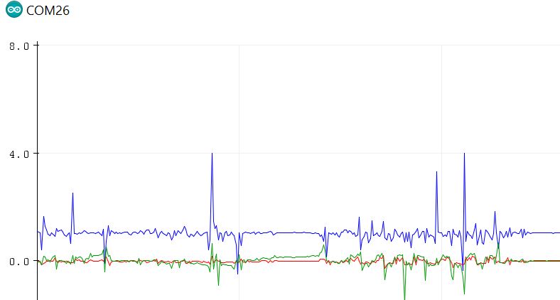
Upload the code to the master
and the slave respectively, connect the USB cable to the slave, open
the serial plotter in your Arduino IDE and show the data is being
plotted in realtime.
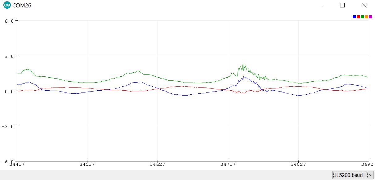
Task 7: Demonstrate the results in a video in your report.
6. Store the received data to the SD card (at the slave side).
Imagine that the sensor and
the master are located at a harsh and out-of-reach environment (like a
horse hoof or a drone), when the object is moving, you need to collect
the accelleration data to somewhere wirelessly. Keep in mind that
wireless is required, not optional. Save the data to an SD card temporary is a very
good option. You can always analyze the data by extracting the files in
a Python/MATLAB script.
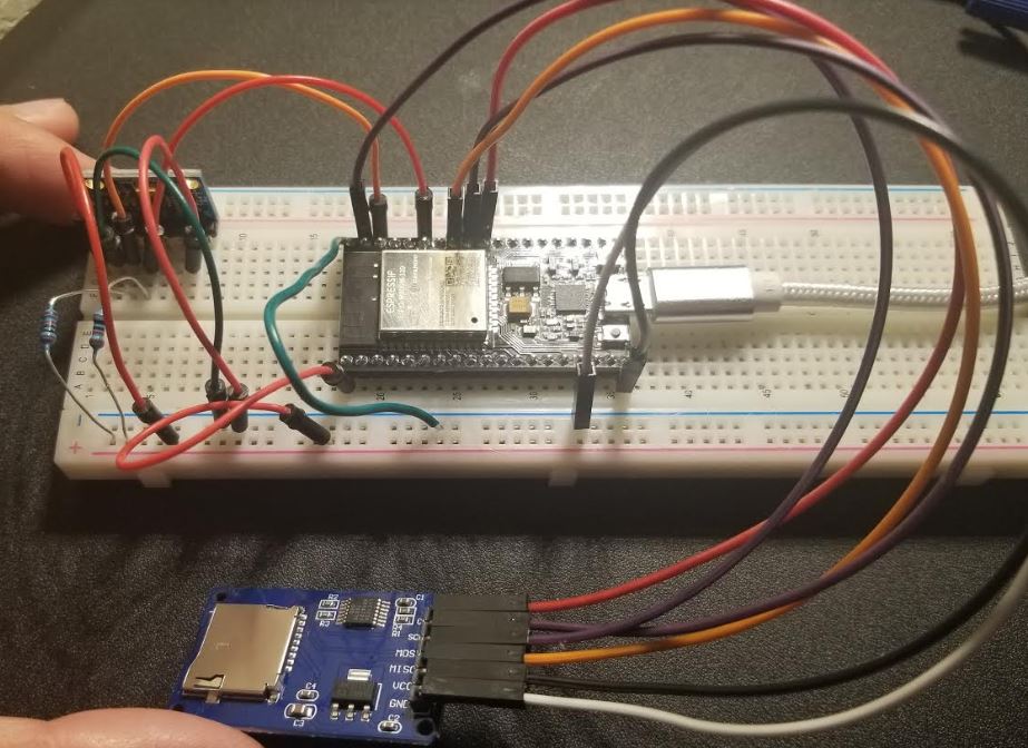
The hardware connection becomes very simple given all the tasks above have been completed.
Add the connections showed in Section 4 in this tutorial:
Again, the VCC pin of the SD
card adapter should be shorted to the 5V pin of the ESP board because
the adapter also has the AMS1117 3.3 V regulator.
Please note that you do not need two breadboard, ONE should have enough space to hold all the circuits.
Task 8:
Design the script to receive the accelleration data from the master
wirelessly by the slave and store the data to the SD card connected to
the slave board.
Task 9:Remove
the division operation being performed on the ESP board, delete
all the unnecessary code for 'debugging purpose', remove the serial
port settings, and get a clean script for the master and the slave
respectively. Plot the saved data in Python (mandatory for CE students)
or MATLAB. The Python example is provided in the Appendix.
Appendix:
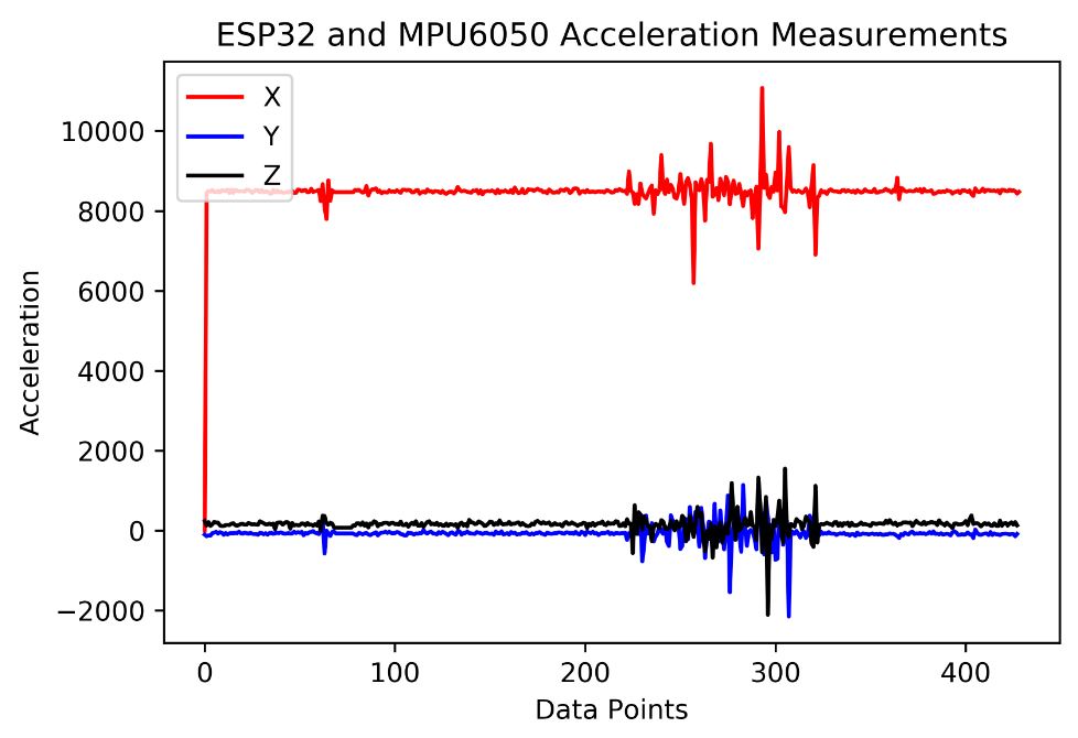
An example Python code to plot the AccX, AccY, and AccZ data in a folder:
The Python code to plot the
data in the three .txt files. It is mandatory for CE students to use
Python to plot. Engineering students can use MATLAB. The figure should
have three data lines, a legend, a title, and X and Y axis labels.
Please note that the numbers in the .txt files are strings. In Python,
you can use the '.split()' function to separate the items into
individual strings and saved in a list. The MATLAB code to extract data
from the files is not provided.
-----------------------------------------
import matplotlib.pyplot as plt
fx=open('AccX.txt','r')
fy=open('AccY.txt','r')
fz=open('AccZ.txt','r')
contentx=fx.read()
contenty=fy.read()
contentz=fz.read()
valx_str=contentx.split(',')
valy_str=contenty.split(',')
valz_str=contentz.split(',')
fx.close()
fy.close()
fz.close()
valx_float_temp=[]
valy_float_temp=[]
valz_float_temp=[]
for numx in valx_str:
try: # The very last string cannot be converted to float
valx_float_temp.append(float(numx))
except:
valx_float_temp.append(numx)
valx_float=valx_float_temp[:-1]# Get rid of the very last unknown symbol
#print(val_float)
for numy in valy_str:
try: # The very last string cannot be converted to float
valy_float_temp.append(float(numy))
except:
valy_float_temp.append(numy)
valy_float=valy_float_temp[:-1]# Get rid of the very last unknown symbol
#print(val_float)
for numz in valz_str:
try: # The very last string cannot be converted to float
valz_float_temp.append(float(numz))
except:
valz_float_temp.append(numz)
valz_float=valz_float_temp[:-1]# Get rid of the very last unknown symbol
#print(val_float)
plt.plot(valx_float, c="red")
plt.plot(valy_float, c="blue")
plt.plot(valz_float, c="black")
plt.legend(["X", "Y", "Z"], loc="upper left")
plt.xlabel("Data Points")
plt.ylabel("Acceleration")
plt.title("ESP32 and MPU6050 Acceleration Measurements")
plt.savefig("Accelerations", dpi=600)
plt.show()
-----------------------------------------
An example plot using the python script above.