Printed
circuit board (PCB) design
is a great skill to have as an engineer in the electrical realm. There
are many
different programs used to design these boards, but the materials and
design
rules are the same.
We will be using Eagle PCB to design our circuits. Eagle
is a free software by AutoDesk, the same
makers of AutoCADD.
AutoCADD is a popular software used to design mechanical
components and create professional dimension sheets. If you are
familiar with
the AutoDesk products, you may have an easy time learning the user
interface of
Eagle. Eagle
is
not like LT Spice in the way that circuits are designed to be
simulated. With Eagle, the circuits are designed as blueprints.
For
this project, the circuit from
version 1 (V1) of the Line Follower project will be turned into a PCB
design. Gerber files will be created, and those may be sent to a
maufacturer to be created!
There
are tutorials for working with Eagle
software that can be foundhere. I
recommend that you go through the
first two tutorials, "PCB Basics" and "Schematics and
Layout," before starting this project.
The other tutorials have useful
information in them as well; however, we will not be needing them for
this
project. Feel free to check them out on your own!
You will probably read
through them in other classes later on here at Fort Lewis College.
If you followed the tutorials for EAGLE
before starting, you already have the SparkFun libraries installed, and
you do not have to redownload it.
The Spark Fun libraries do not
include what is included in the LineFollowerV2 library, so you will
still need to download that one.
Follow the same steps as in the
Eagle tutorial for adding the LineFollwerV2 library and activating it
for use
in the EAGLE control panel.
3. Instructions
If Eagle software is not already installed on the machine, it can be
found to download for free here. If the machine is on the Fort Lewis campus,
it can be found by doing a quick search for "Eagle" through the start
bar.
The
Eagle interface can be a bit confusing and frustrating to use as a
beginner. Some tips and tricks for navigating the software can be found
in the video below.
You may want to change the quality setting to 720p60 to read the text
better.
Part 1 - Drawing the Circuit
To begin, it may be a good idea to draw out the circuit before
drawing it in
Eagle. Let's look at the schematics of some of the components from the
circuit
of V1.
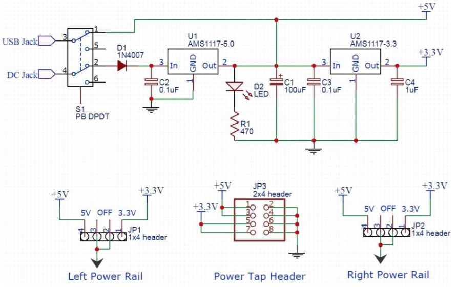
The DC-DC Voltage Converter:
This has extra components on it that we will not need; Components like
the USB jack, the jumper pins, the 3.3V regulator system, and the rail
outputs.
We will not be using rails since we are not
building the circuit on a breadboard. Let's see if we can simplify this
by removing
those components.
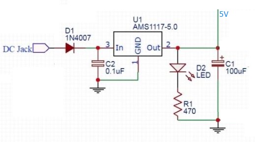
It should now look something like this:
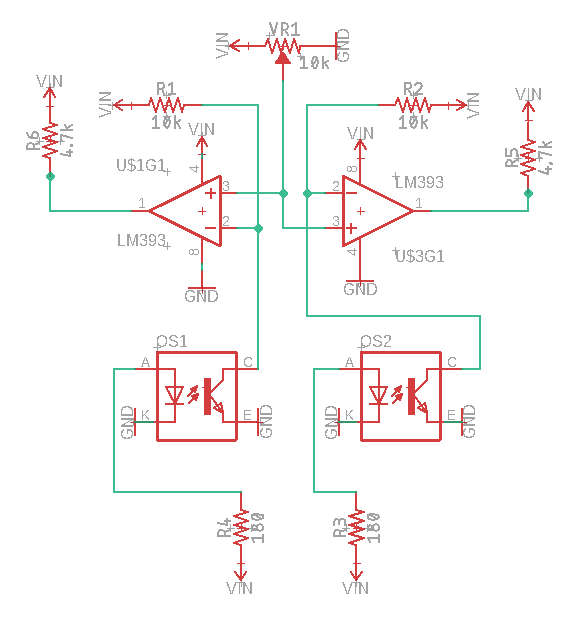
The schematic for the IR Sensor module with TCRT5000 sensors can be
found here. For our purposes, we will remove the analog
out pin, and we will switch the connection of the non-inverting
terminal and the inverting terminal.
This will allow us to remove the hex buffer/inverter! We also will only
need one op-amp and one potentiometer to calibrate the sensors, so we
will remove one of each from the circuit for the second TCRT sensor.
The IR sensor circuit should now look something like this:
The pin out maps of all the parts used in the circuit for V1 that
will also be used on the PCB can be found here.
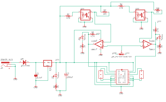
When put altogether, the circuit should look something like this:
Part 2 - Drawing the PCB Schematic
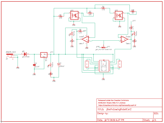
Now the schematic that will be used for the PCB design can be drawn.
Create a new project in Eagle PCB; I will be calling mine "LineFollower"
Create a new schematic within the project, and place a frame aligned
with the crosshair. This will set the board's orientation. Add the
proper components needed for the circuit to the schematic sheet.
These
will be outlined in red. The crosshair on the symbol is where you can
click to move the piece around. Once they are placed, you can begin
adding the wires and junctions.
These will be green, and the junctions are
represented with circles. The junctions are where the wires connect.
Mine looks like this:
Part 3 - Designing the PCB Layout
Now that the schematic is completed, the layout of the board can be
arranged! This is the fun part! It's like a giant puzzle with so many
different ways to solve it!
There are a few rules you'll need to
follow to ensure the circuit works as intended. Rules such as: not
letting wires cross unless they are on opposite planes to prevent a
short,
and ensuring that the proper amount of space is between
components to make sure no through holes or pins
connect to anything undesired. These rules, and more, are also covered
in the Eagle PCB tutorials.
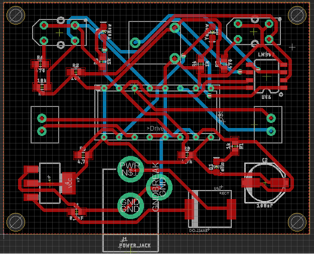
Move the components around in a way that flows well. It is good
practice to leave at least 1.5mm of space between components. They
would be soldered to the PCB by hand,
and it would be hard to do so if
the components are too close together. Once the parts placement is
complete, you can begin laying the
wires!
Utilize vias and both planes of the PCB to wire everything
together, and once you're done, check for errors with the "ERC" error
checking tool. Once that is clear with no issues, run the "Ratsnest"
tool to check for errors as well;
When no errors are present, it should return that there is "nothing
to do!"
Mine looks something like this:
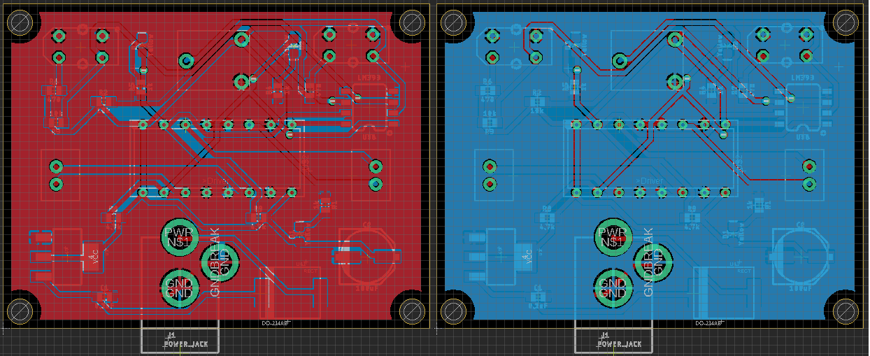
When there are no errors, and everything is wired properly, it is time
to layout the copper pour. These copper pours are a sheet-pour of
copper on each side of the board to connect the grounding wires
together.
To do so, use the polygon tool to outline the edge of the
PCB. Ensure that the top layer of the PCB is selected. Once it is
outlined, run the ratsnest tool again.
This should "pour" the copper
onto the board. Do this again on the bottom layer.
Mine looks like this after the copper has been "poured." The view from
the top layer on the left, and the bottom layer on the right:
Once the copper is done being "poured," the PCB should be ready for the
Gerber files to be generated and to be sent off to be made!
Congratulations on designing your first PCB!!
Now you can generate the Gerber files and submit them to be made! A
tutorial on generating Gerber files can be found here.
Part 4 - Soldering the components to the PCB
Soldering
the components to the PCB
can be done a few ways. You can use solder paste heated with a hot air
blower,
or you can solder it by hand with a soldering iron.
Either way, you will need flux to prepare the metals to be bonded. Flux
is a
slightly acidic paste that is used to remove the thin, oxidized layer
of the
metal so the solder can bond with the metal.
Once the flux has been added to
the pads and through-holes, you can then place the part where it’s to
be soldered
and begin soldering.
I
suggest applying the flux as you go instead of putting
it on all the pads before soldering any components. It's also a good
idea to go
from shortest component to tallest when deciding what to solder next.
For surface mounted devices (SMDs) like the op-amp, diodes, resistors,
etc.,
you can place the component on the board with the tweezers to steady in
place.
Then get a small amount of solder on the tip of the iron. Heat the pad
under
the component while putting the solder to the pad. You will want the
solder to
wrap around the pins of the component.
If the component is on there, but not
flush with the board, you can usually put the iron to the pad, without
any
solder on the iron, and heat the pads.
Usually gravity will do its thing, but
sometimes you may have to use the tweezers to adjust it.
Also, do not worry if
you get solder too much solder on there, you can always try to remove
excess by
wiping it off with your clean soldering iron.
You also won't get the pads
shorted together if there is solder mask between them to keep them
separate. Solder mask is a plastic, so the solder will not bond to it.
For
through-hole components, like the TCRT pairs, driver holster, DC jack,
etc., you
can place the pins through the holes from the top of the board, steady
it with
your fingers,
and flip the board over, and slip your fingers out once you have
the component steadied on a surface.
You
don't want to be touching the
component while soldering, especially if it's small; they get hot as
you heat
the pins, and you may burn yourself.
Once
the component is secure, you
can take a clean soldering iron, and heat the pins.
After a few seconds, the
pins should be hot, and that is when you can take a piece of soldering
wire and
touch it to the iron and pin to coat the pin/fill the hole with solder.
If the through-hole is larger than the pin being soldered to it, you
can fill
the hole with solder!
Just
be careful and watch your fingers on the
solder wire; You don't want to accidentally touch the iron!
After all the components are soldered to the PCB, you can test the
circuit with
a multimeter.
Power up the circuit and use the voltage probe setting of the
multimeter to check that the voltages are correct at each node of the
PCB.
Make sure to calibrate the sensors by ensuring the potentiometer is
outputing 2.5V to the comparator! Once you know it does, your
PCB should now be ready to put on the car!
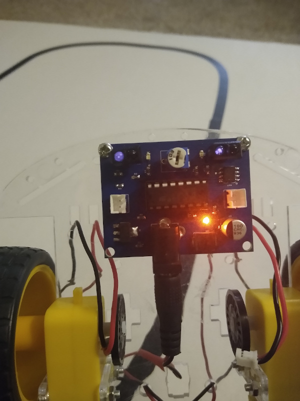
Check to see that your emitters on the TCRTs are working properly.
Do this by powering up the PCB, and looking at the sensors with a
camera.
The camera will be able to pick up the infrared light that you cannot
see with your eyes.
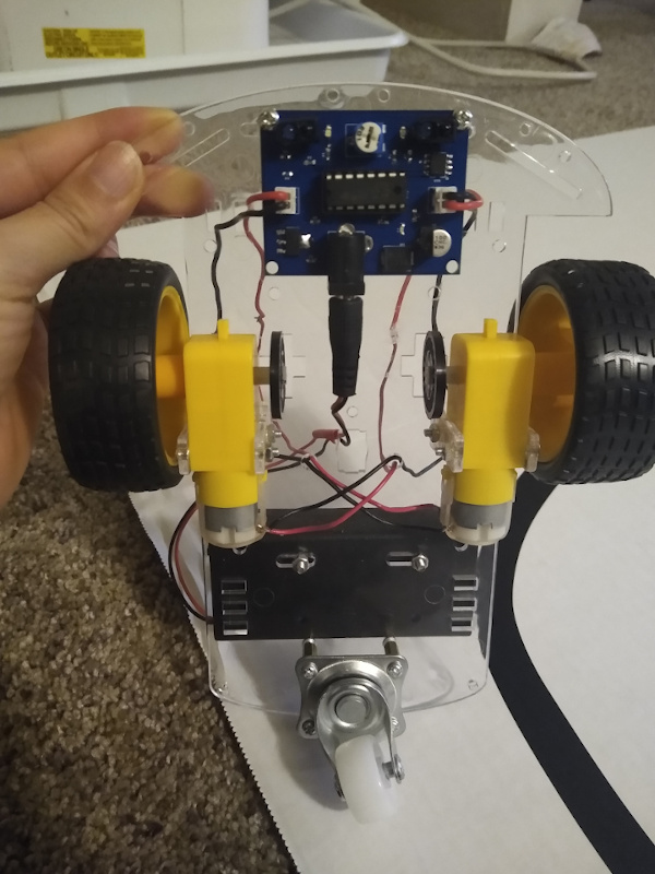
Since
the sensors are on the PCB, we need to get the sensors closer to
the
ground. To do this, we will use more stand-offs.
Assemble two pairs of 2 standoffs
together like you did in the V1 tutorial, and attach one to each of the
stacked
standoffs that are already on the chassis of the line follower after
removing
the TCRT5000 sensor modules from V1.
You may need to drill two holes in the chassis for the bottom holes on
the PCB.
Assemble two pairs of 4 standoffs like you just did, and finish
securing the
PCB to the car.
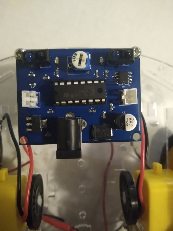
The line follower should be ready to go!
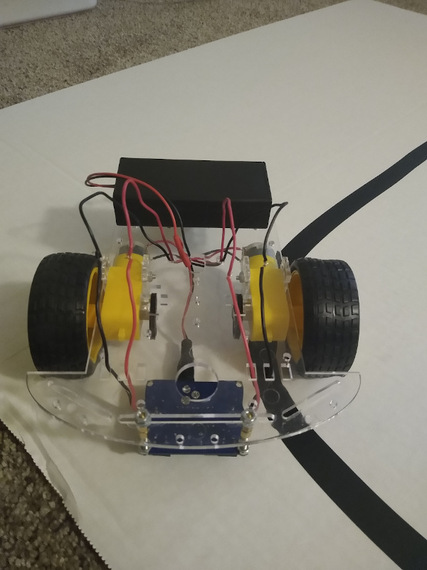
This is what the car looks like once the PCB is completed:
A demonstration of the V2 line follower is shown below.