Tutorial
3 A 3-bit Adder/Subtractor for 2's Complement Signed Binary
Numbers
Outcome of this lab:
1. An ability to program an advanced
sequential logic using Verilog Hardware Description Language.
2. An ability to buid a 3-bit adder/subtractor in 2's complement, and
display the result in decimal.
3. An ability to verify the logic using FPGA. We will use the Basys3 FPGA board.
Instructions:
Use the updated constraint file here.
1, Understand the 3-bit adder/subtractor in 2's complement:
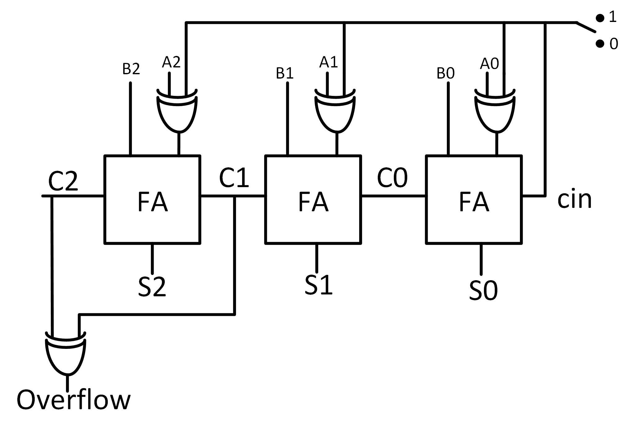
Addition/Subtraction of 2's complement signed
binary numbers:
When
the control bit is switched to '1', A XOR 1 = A not, so A is inverted,
and plus 1 (at cin), which is exactly the 2's complement of A, the
system will perform 'B+(-A)', which is 'B-A'; when the control bit is
switched to '0', A XOR 0 = A, and cin=0, the system will
perform 'B+A'.
Overflow:
As the definition of 'overflow', if you have negtive + negative =
positive, or positive + positive = negative, then the result of the
addition is out of range, you need an extra bit to represent the
result. The overflow indicator will show you when do you need to count
an extra bit.
Your code should be able to tell FPGA what is the extra bit in order to
display the correct corresponding decimal number.
Step 1:
Use switches as the 3-bit inputs, use 'leds' to show the binary
results.
Step 2:
Use
switches as the 3-bit inputs, use seven-segment displays to show the
decimal result, make sure have the 'minus' sign in front of the decimal
number if the result is negative.
The verification should be recorded in videos in your html report.
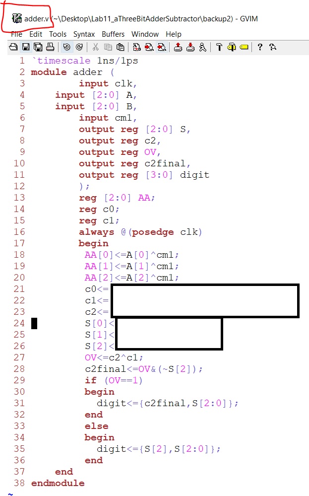
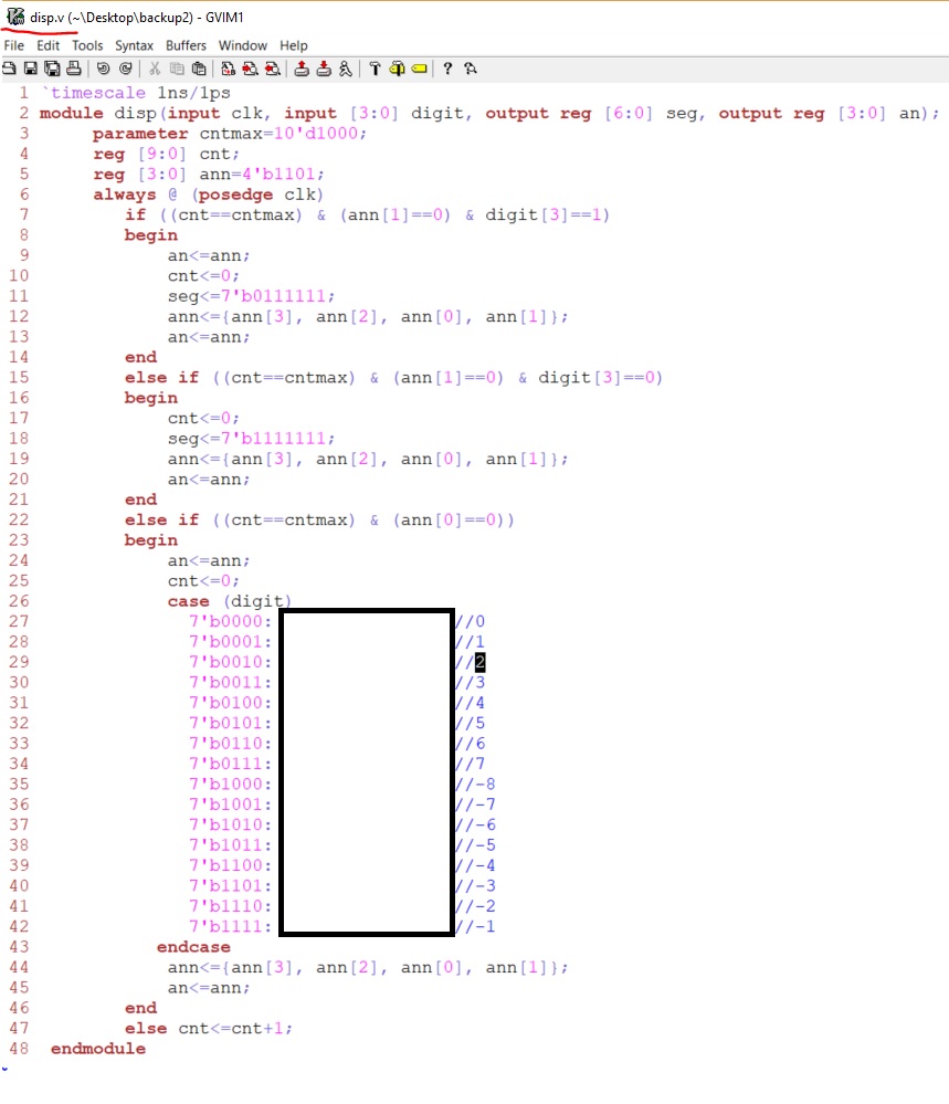
Part of the verilog code is given below. I designed three
verilog modules: the adder module, the display module, and the
'top' module. The 'top' module is actually the testbench, which is
easy. The 'adder' module is the calculator to deliver the final 4-bit
result. The display module will take the result from the 'adder' module
and display the results in the LEDs and the SSD.