Outcome of this lab:
1. An ability to program an advanced combinational logic using Verilog Hardware Description Language.
2. An ability to verify the logic using simulations in Vivado.
3. An ability to verify the logic using FPGA. We will use the Basys3 FPGA board.
Instructions:
Use the updated constraint file here.
1. Using Verilog and Vivado to demonstrate the following combinational logic blocks in both simulation and on the board (switches/leds):
1) OR 2) XOR 3) Inverter 4) 2-bit full adder 5) 8-input And 6) 4-1 MUX (can use an embedded condition: y=s1?(s0?d3:d2):(s0?d1:d0))
2. Using Verilog and Vivado to design a 'Running LED' program on the FPGA board. Use 4 LEDs on the board, turn on each of them for 1 second one-by-one. The demonstration video can be found in the following: Make sure you have a 'reset' function to reset the LEDs to the original state.
Hints for this program:
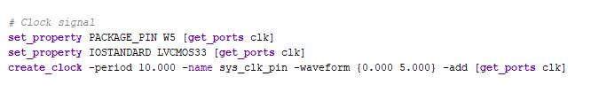
1) The timing for the running led is controlled by the on-board oscillator (100 MHz). To convert it to a 1 second timer, we need to count for 100 MEG times and then do something. Before you code anything, make sure you enable the clock in your constraint file.
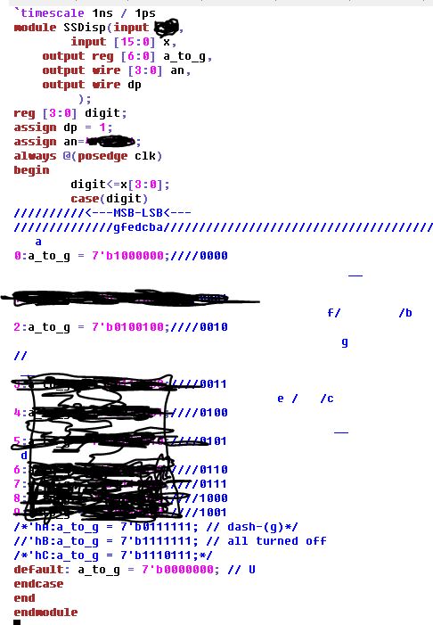
2) The main frame for the module can be:

I crossed out some of the parameters/variables in the program, complete this yourself.
3) Design a testbench for this module. Use sw[0] as 'rst' (reset, which is able to restart everything when rst=1), use LED[3:0] as the 4 running LEDs. Demonstrate it on your FPGA board. (directly download the bit file to the FPGA, no need to program it in the bin file and store the code into the on-board memory).
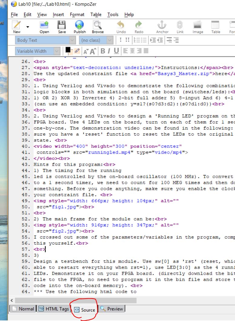
*** Use the following html code to publish your mp4 video on your website: (rename the mp4 filename if it is different from yours)
Copy and paste this code into the source code of your lab report:
<video width="400" height="300" position="center"
controls="" src="runningled.mp4" type="video/mp4">
</video><br>
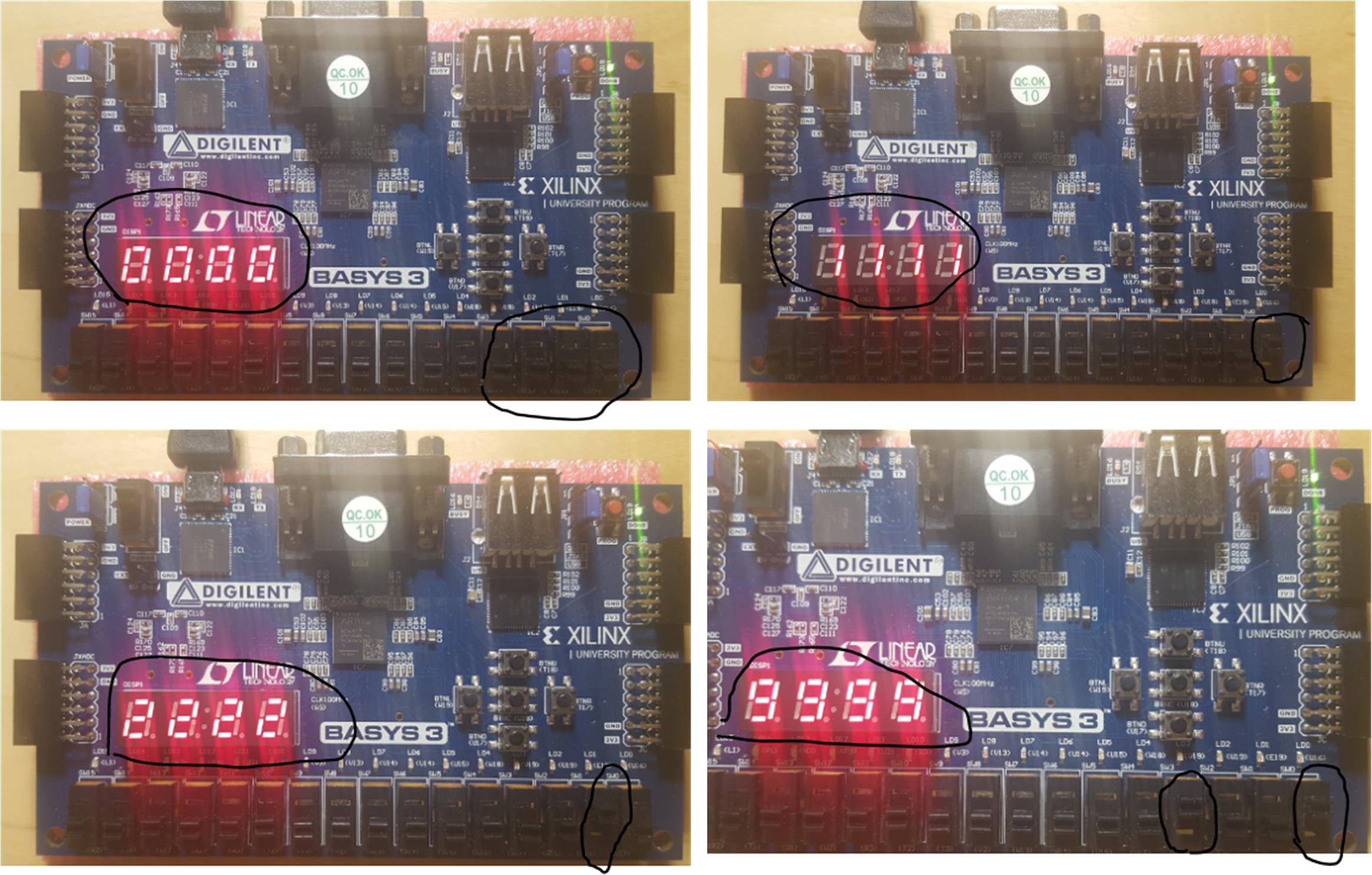
3. Interface the switches with the 7-segment display on the board. (make sure you have the '##7 segment display' part in your constraint file uncommented)
The final result should show numbers 0-9. There are some examples in the following figure.
sw[3:0] provide binary inputs and the 4 7-segment display show the corresponding decimal numbers.
Hints:
You can complete this outline, and generate a testbench for it.
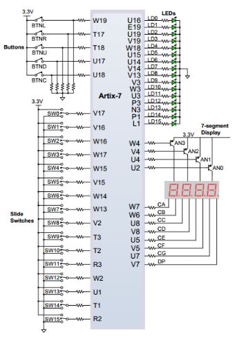
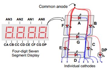
The circuit map for the 7-segment display and the FPGA can be found in the datasheet of Basys3 (in the front of this lab instruction). The two major connections:
4. Modify the code, disable any 3 of the 7-segment displays and only show the number on one of the displays.
Please note that:
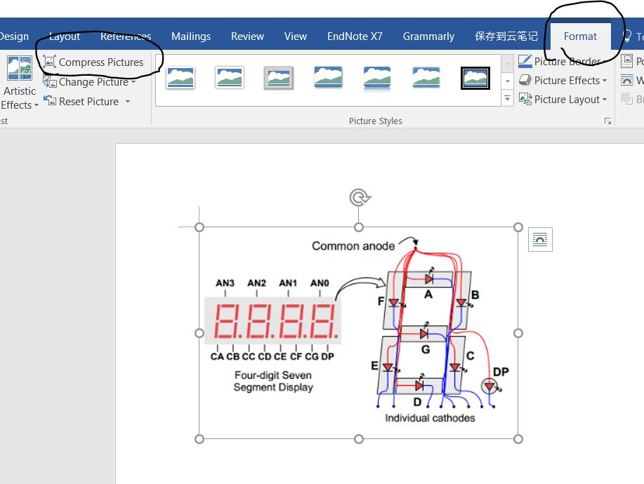
1) Report all your results with figures. Compress your figures before you upload it. You can use 'snipping tools' or you can copy your figure into Word and then compress it. I'll take points off if your report is too big to download.
2) Include a discussion or conclusion session in your report if you never did this before.