EEPROM Applications
1. Update, Read, and Clear the EEPROM in Arduino UNO.
Credit given to: EEPROM with Arduino - Internal & External (dronebotworkshop.com)
An
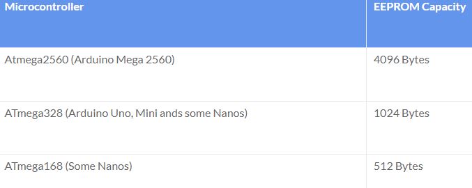
EEPROM has a very small amount of storage, in fact, EEPROM capacities
are commonly measured in Bits as opposed to Bytes. Since they only
store a small amount of data they don’t consume a great deal of
current, making them ideal for battery and low-powered applications.
EEPROM is similar to flash memories but a lot smaller.
No
limits on read but has limits on the number of writes (~ 100k - 2
millions times), so don't put it in a loop, but only for necessary
calibration or updates, for example, a TV user set up TV brightness
values and these values will stay when the TV got shut off our powered
off. Another example could be a recent project my undergraduate
students worked on - update WiFi credentials on an IoT device.
Never
put the EEPROM_write or EEPROM_update into Arduino's loop() function,
it is running at 16 MHz which will write to it for thousands of times
in a few mili seconds!!
Sizes of some AVR EEPROMs.
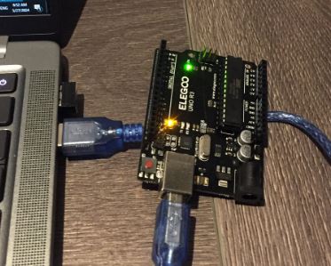
Simply plug in your Arduino board to the computer.
Open an Arduino IDE, use this EEPROM_update.txt code to read values (incrementing by 1 every 300 mili seconds).
#include <EEPROM.h>
/** the current address in the EEPROM (i.e. which byte we're going to write to next) **/
int address = 0;
int val=0;
void setup() {
/** EMpty setup **/
}
void loop() {
/***
Update the particular EEPROM cell.
these values will remain there when the board is
turned off.
***/
EEPROM.update(address, val);
val+=1;
/***
The function EEPROM.update(address, val) is equivalent to the following:
if( EEPROM.read(address) != val ){
EEPROM.write(address, val);
}
***/
/***
Advance to the next address, when at the end restart at the beginning.
Larger AVR processors have larger EEPROM sizes, E.g:
- Arduno Duemilanove: 512b EEPROM storage.
- Arduino Uno: 1kb EEPROM storage.
- Arduino Mega: 4kb EEPROM storage.
Rather than hard-coding the length, you should use the pre-provided length function.
This will make your code portable to all AVR processors.
***/
address = address + 1;
if (address == EEPROM.length()) {
address = 0;
}
delay(300); // 300 mili seconds
}
Let it run for at least 30 seconds.
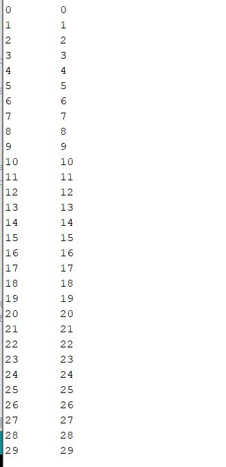
Then, use this EEPROM_read.txt to read the values stored in the Arduino EEPROM
#include <EEPROM.h>
// start reading from the first byte (address 0) of the EEPROM
int address = 0;
byte value;
void setup() {
// initialize serial and wait for port to open:
Serial.begin(9600);
while (!Serial) {
; // wait for serial port to connect. Needed for native USB port only
}
}
void loop() {
// read a byte from the current address of the EEPROM
value = EEPROM.read(address);
Serial.print(address);
Serial.print("\t");
Serial.print(value, DEC);
Serial.println();
/***
Advance to the next address, when at the end restart at the beginning.
Larger AVR processors have larger EEPROM sizes, E.g:
- Arduno Duemilanove: 512b EEPROM storage.
- Arduino Uno: 1kb EEPROM storage.
- Arduino Mega: 4kb EEPROM storage.
Rather than hard-coding the length, you should use the pre-provided length function.
This will make your code portable to all AVR processors.
***/
address = address + 1;
if (address == EEPROM.length()) {
address = 0;
}
/***
As the EEPROM sizes are powers of two, wrapping (preventing overflow) of an
EEPROM address is also doable by a bitwise and of the length - 1.
++address &= EEPROM.length() - 1;
***/
delay(500);
}
You will see the following results
Then run the EEPROM_clear.txt code to clear up the EEPROM.
#include <EEPROM.h>
void setup() {
// initialize the LED pin as an output.
pinMode(13, OUTPUT);
/***
Iterate through each byte of the EEPROM storage.
Larger AVR processors have larger EEPROM sizes, E.g:
- Arduno Duemilanove: 512b EEPROM storage.
- Arduino Uno: 1kb EEPROM storage.
- Arduino Mega: 4kb EEPROM storage.
Rather than hard-coding the length, you should use the pre-provided length function.
This will make your code portable to all AVR processors.
***/
for (int i = 0 ; i < EEPROM.length() ; i++) {
EEPROM.write(i, 0);
}
// turn the LED on when we're done
digitalWrite(13, HIGH);
}
void loop() {
/** Empty loop. **/
}
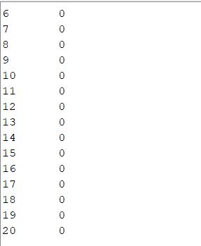
After
clearing up the EEPROM, you should have only 0's left in the memory.
Use the EEPROM_read code to read and verify. Here is the results I got
from my board:
2. RGB LEDs
The longest is GND and the ONE next to it is Red, the TWO pins next to it are GREEN and BLUE.
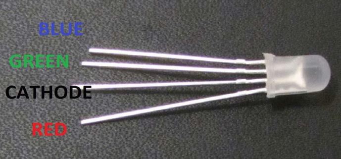
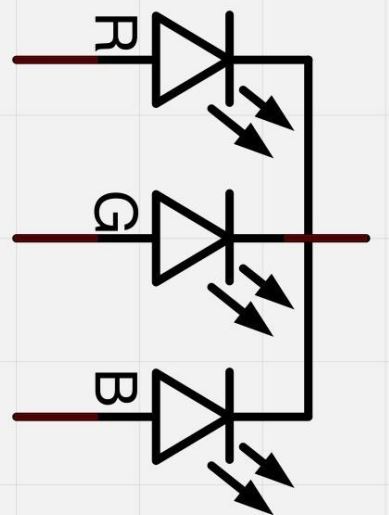
It is using the common cathode connection.
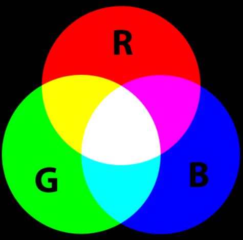
The combination of various intensities of R, G, and B will form different colors.
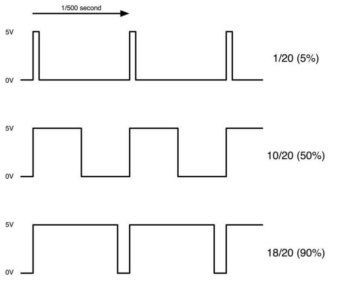
PWM (Pulse Width Modulation) deliver various amount of energy to the output by using varying pulse widths.
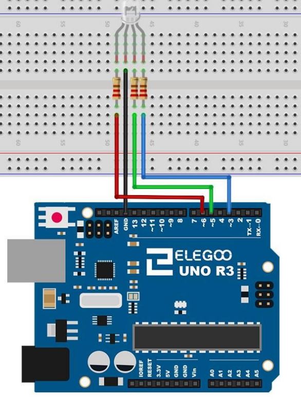
Hardware connection.
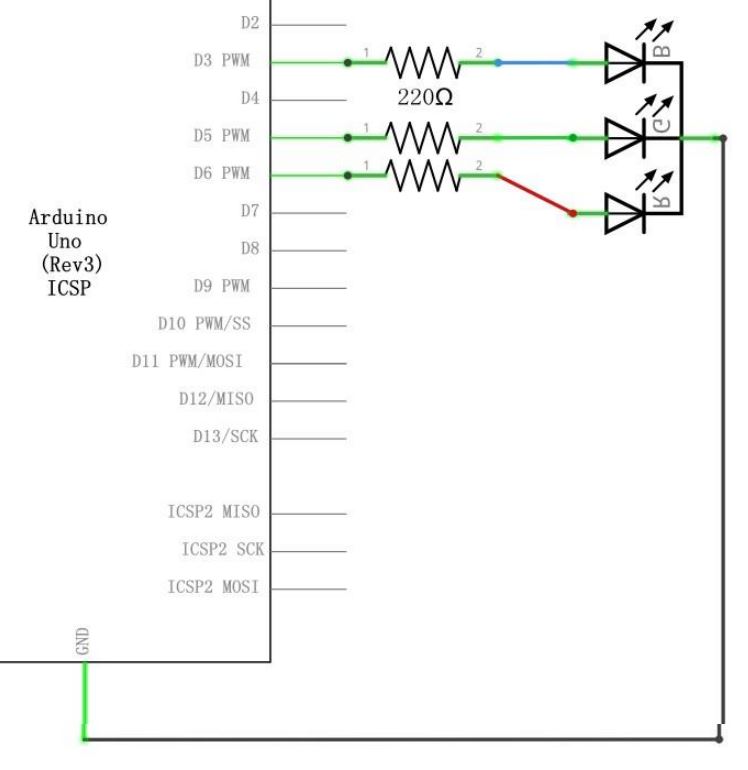
Make sure the GND pin is connected to the circuit correctly.
Here is the code (RGB_ex1.txt) to switch the color between R, G, and B with 1 second intervals.
const int PIN_RED = 6;
const int PIN_GREEN = 5;
const int PIN_BLUE = 3;
void setup() {
pinMode(PIN_RED, OUTPUT);
pinMode(PIN_GREEN, OUTPUT);
pinMode(PIN_BLUE, OUTPUT);
}
void loop() {
// color code #00C9CC (R = 0, G = 201, B = 204)
analogWrite(PIN_RED, 0);
analogWrite(PIN_GREEN, 0);
analogWrite(PIN_BLUE, 255);
delay(1000); // keep the color 1 second
// color code #F7788A (R = 247, G = 120, B = 138)
analogWrite(PIN_RED, 255);
analogWrite(PIN_GREEN, 0);
analogWrite(PIN_BLUE, 0);
delay(1000); // keep the color 1 second
// color code #34A853 (R = 52, G = 168, B = 83)
analogWrite(PIN_RED, 0);
analogWrite(PIN_GREEN, 255);
analogWrite(PIN_BLUE, 0);
delay(1000); // keep the color 1 second
}
Here is another example code (RGB_LED_dim.txt) to show varying colors but by dimming them and having smooth transitions.
//www.elegoo.com
//2016.12.8
// Define Pins
#define BLUE 3
#define GREEN 5
#define RED 6
void setup()
{
pinMode(RED, OUTPUT);
pinMode(GREEN, OUTPUT);
pinMode(BLUE, OUTPUT);
digitalWrite(RED, HIGH);
digitalWrite(GREEN, LOW);
digitalWrite(BLUE, LOW);
}
// define variables
int redValue;
int greenValue;
int blueValue;
// main loop
void loop()
{
#define delayTime 10 // fading time between colors
redValue = 255; // choose a value between 1 and 255 to change the color.
greenValue = 0;
blueValue = 0;
// this is unnecessary as we've either turned on RED in SETUP
// or in the previous loop ... regardless, this turns RED off
// analogWrite(RED, 0);
// delay(1000);
for(int i = 0; i < 255; i += 1) // fades out red bring green full when i=255
{
redValue -= 1;
greenValue += 1;
// The following was reversed, counting in the wrong directions
// analogWrite(RED, 255 - redValue);
// analogWrite(GREEN, 255 - greenValue);
analogWrite(RED, redValue);
analogWrite(GREEN, greenValue);
delay(delayTime);
}
redValue = 0;
greenValue = 255;
blueValue = 0;
for(int i = 0; i < 255; i += 1) // fades out green bring blue full when i=255
{
greenValue -= 1;
blueValue += 1;
// The following was reversed, counting in the wrong directions
// analogWrite(GREEN, 255 - greenValue);
// analogWrite(BLUE, 255 - blueValue);
analogWrite(GREEN, greenValue);
analogWrite(BLUE, blueValue);
delay(delayTime);
}
redValue = 0;
greenValue = 0;
blueValue = 255;
for(int i = 0; i < 255; i += 1) // fades out blue bring red full when i=255
{
// The following code has been rearranged to match the other two similar sections
blueValue -= 1;
redValue += 1;
// The following was reversed, counting in the wrong directions
// analogWrite(BLUE, 255 - blueValue);
// analogWrite(RED, 255 - redValue);
analogWrite(BLUE, blueValue);
analogWrite(RED, redValue);
delay(delayTime);
}
}
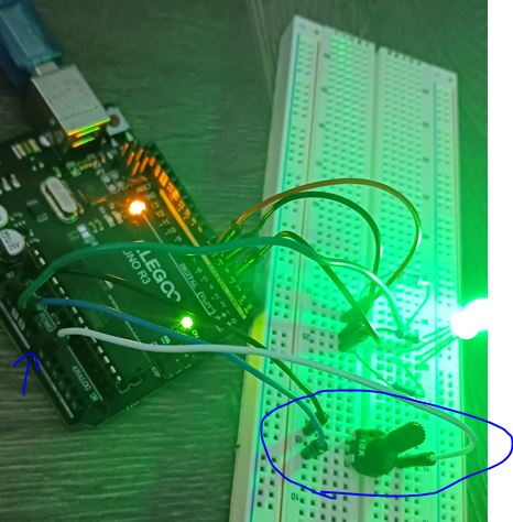
3. Setup the RGB color by a potentiometer and save it in the EEPROM
Connect
a potentiometer to A0, the analog input pin. use analogRead(0) to read
from it. You may need to use the mapping function in Arduino to
converrt the 10-bit ADC result (0-1023, to 0-255). Here is the webpage for examples.
The
value from A0 can be written into address 0 when you calibrate it. Make
sure that you don't put the EEPROM.write() function directly in the
loop. It'll constantly being written and we know that EEPROM can only
be written for 10k times!! So keep the following writing command into
an IF statement, only when you press the the button, it is written into
the EEPROM.
The writting function:
EEPROM.write(address, val)
In the loop function, you read from EEPROM to show the color that was set up by the previous user.
You
must be wondering what is the difference between using EEPROM or not
using EEPROM since the setup() function will read the LED setting value
anyway.
Let's
assume that the setting was done by an engineer who bring a calibration
equipment (the potentiometer in this case) to set up the values. Once
the values are read by the MCU, the equipment (the potentiometer in
this case) was removed from the MCU. Imagine that if we set it up and
remove the potentiometer, if we don't use EEPROM, when we restart
Arduino, the setup() function will read Nothing from A0 and it will not
be able to memorize the previous setting.
Tasks:
1. Run all the examples in Sections 1 and 2.
2. Design the program to implement the functionality in Section 3.