Final Project: ADC and SPI
Name: Taylor Schermer
Email: tschermer@fortlewis.edu
Click here to access my presentationTask:
Design a project that takes an analog signal from the potentiometer that is then digitized by the ADC in your Basys3. Then connect the digital signal to the input of the SPI port. Use the 5V/3.3V level shifter in beteween the Basys3 and the Arduino SPI ports. Finally using Arduino to send the signal to the serial monitor for display.
The XADCdemo module showcases the usage of an XADC (Xilinx Analog-to-Digital Converter) to interface with analog inputs and control external devices such as LEDs and an SPI device. The module accepts a 100 MHz clock signal (CLK100MHZ), along with various analog inputs such as vauxp6, vauxn6, vp_in, and vn_in. The module also has SPI communication-related inputs (ss and sck) and outputs such as miso for the controller-in peripheral-out signal. An instance of the XADC module (xadc_wiz_0) processes the analog input from my potentiometer and outputs data and a ready signal. When the ready signal is high, the code assigns the upper 8 bits of the data output from the XADC to the upper 8 bits of the led output. Finally, there is an instance of the SPI follower transmitter (SPI_follower_transmitter) that handles SPI communication, using the upper 8 bits of the data output from the XADC and the SPI-related inputs.
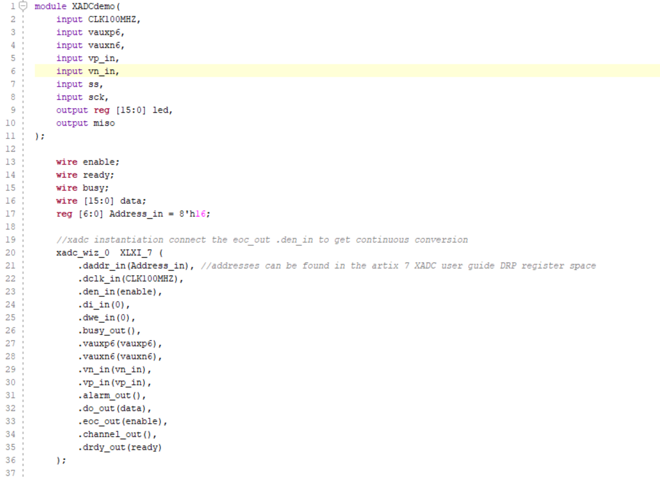
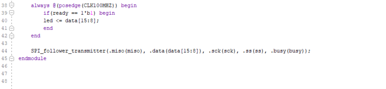
Figure 1. Basys3 ADC Code
The SPI_follower_transmitter module implements an SPI (Serial Peripheral Interface) follower transmitter that handles data transmission over the SPI bus. The module outputs a controller-in peripheral-out (miso) signal carrying data to the SPI controller (Arduino), and a busy signal indicating whether the module is actively transmitting data. It receives an 8-bit data input, as well as the SPI clock (sck) and chip select (ss) signals. The module operates based on a simple state machine with three states: RDY, TRANSMIT, and STOP. In the RDY state, it waits for the ship select signal to go active, at which point it begins data transmission, setting the miso signal to the current data bit and transitioning to the TRANSMIT state. It continues transmitting bits one by one until all data is sent, then transitions to the STOP state, where it resets for the next transmission.
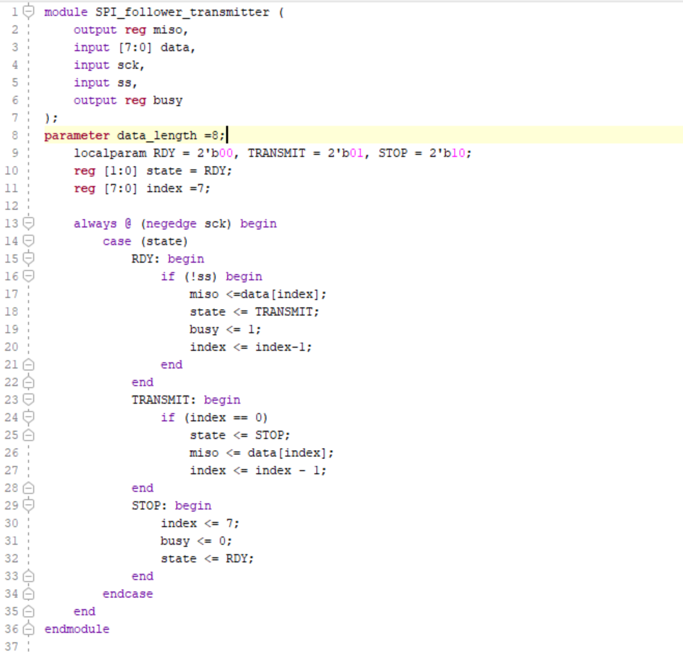
Figure 2. Basys3 SPI Follower Transmitter Code
My code is designed to run on an Arduino as a controller for SPI. It uses the SPI (Serial Peripheral Interface) library to communicate with an SPI device. In the setup() function, the code configures the SPI settings and initializes the required pins. It sets the serial communication speed to 115200 baud using Serial.begin(115200). It then configures pins 13 (sck) and 10 (ss) as output pins and pin 12 (miso) as an input pin using pinMode(). The SPI clock divider is set to SPI_CLOCK_DIV32 to adjust the clock speed, and the bit order is set to MSBFIRST (most significant bit first). The data mode is set to SPI_MODE0, indicating the clock polarity and phase settings for SPI communication. The chip select (ss) pin is set high to deactivate the SPI follower initially. The loop() function is the main routine that runs repeatedly. In each iteration, the function begins by pulling the ss pin (pin 10) low to start communication with the SPI follower. The code then makes a series of SPI.transfer(0) calls, which transfer data from the controller to the follower. Each SPI.transfer(0) call sends a byte of data (0) and receives a byte of data from the follower. The ss pin is set high between each data transfer to stop communication temporarily. The received data is stored in variables (receivedData, receivedData1, ... receivedData8) in each call. After receiving the data, the code prints the last received byte (receivedData8) to the serial console using Serial.println(receivedData8). The function then waits for one second (delay(1000)) before repeating the loop. Due to issues with getting my clocks aligned for my controller and follower, by pulling from the SPI eight times, then displaying the eighth value, I was able to align the clocks and get accurate results.
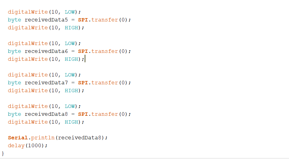
Figure 3. Arduino SPI Controller Receiver Code
Verification:
Here are my results:
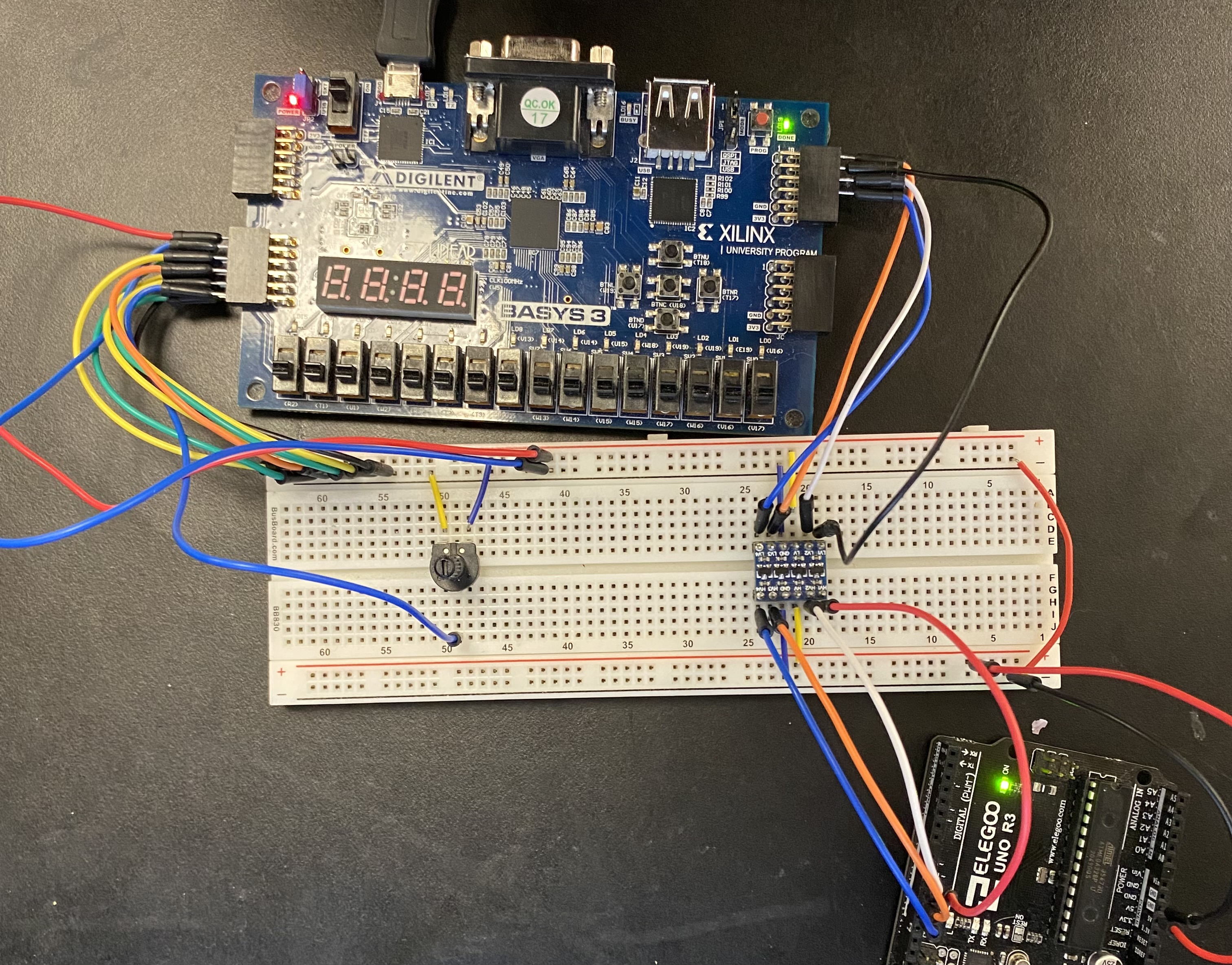
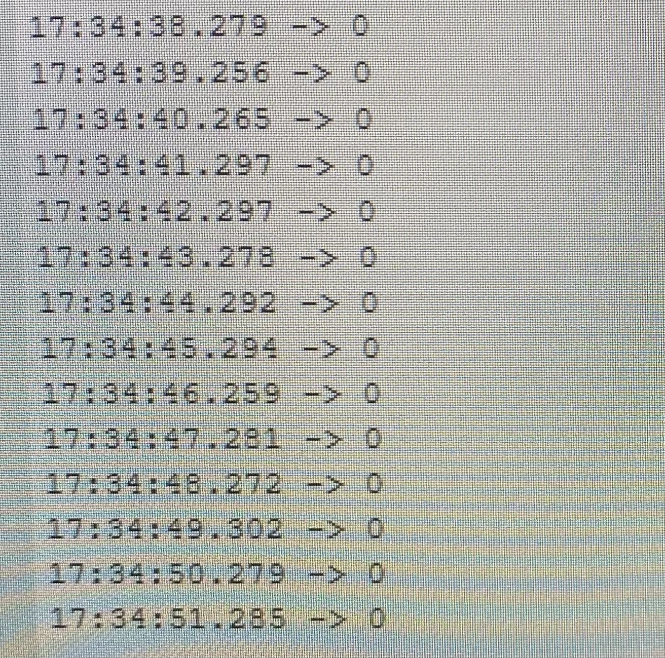
Figure 4. Results for 0 in decimal.
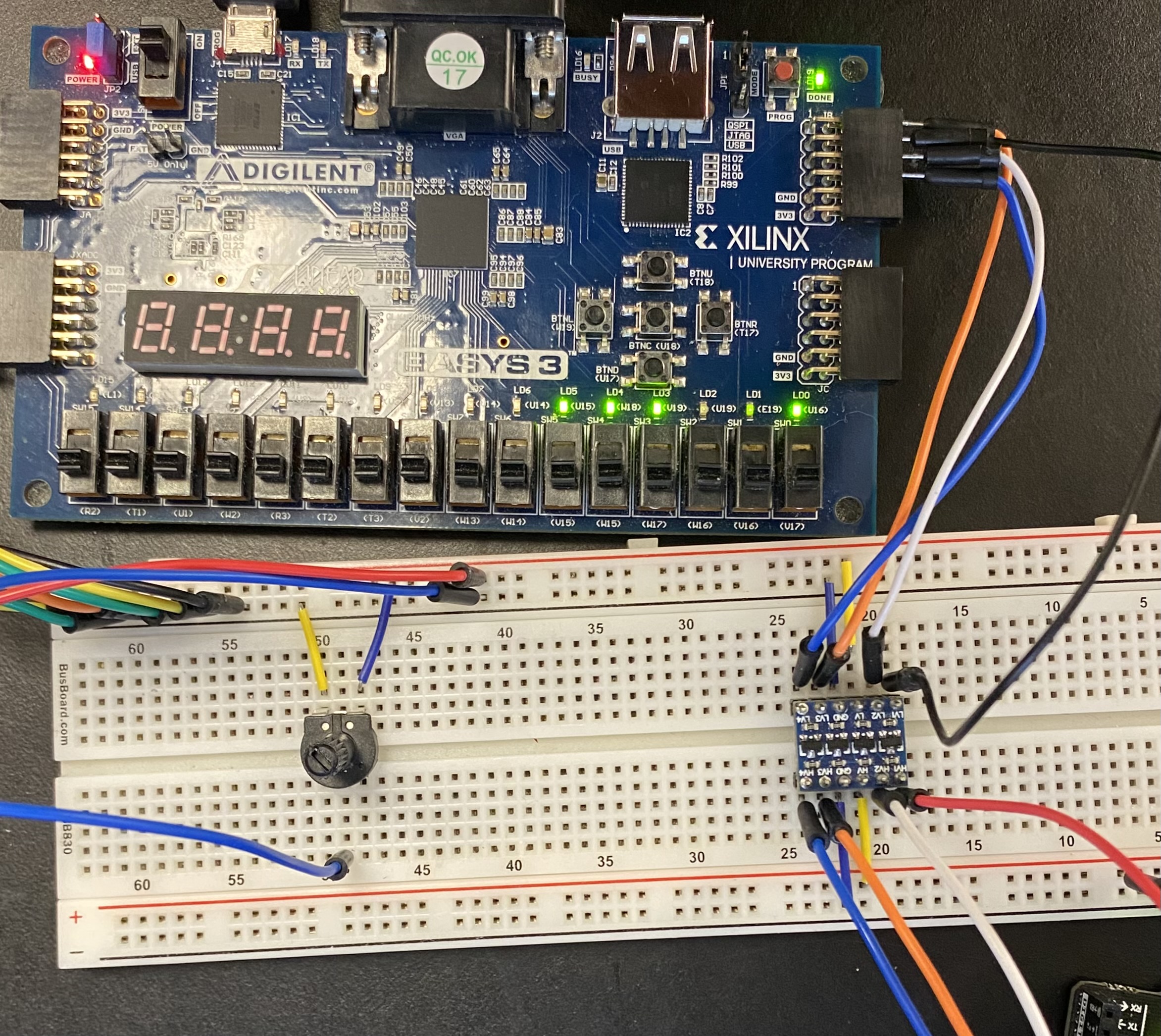
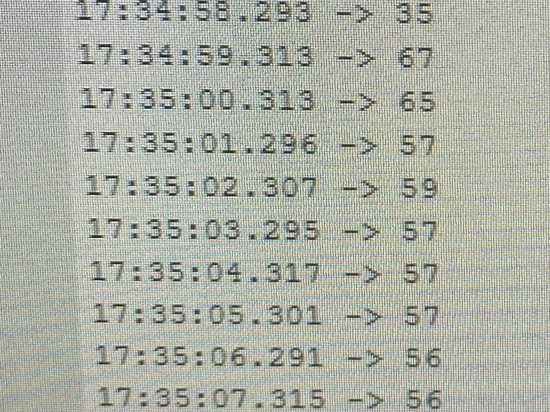
Figure 5. Results for 57 in decimal.
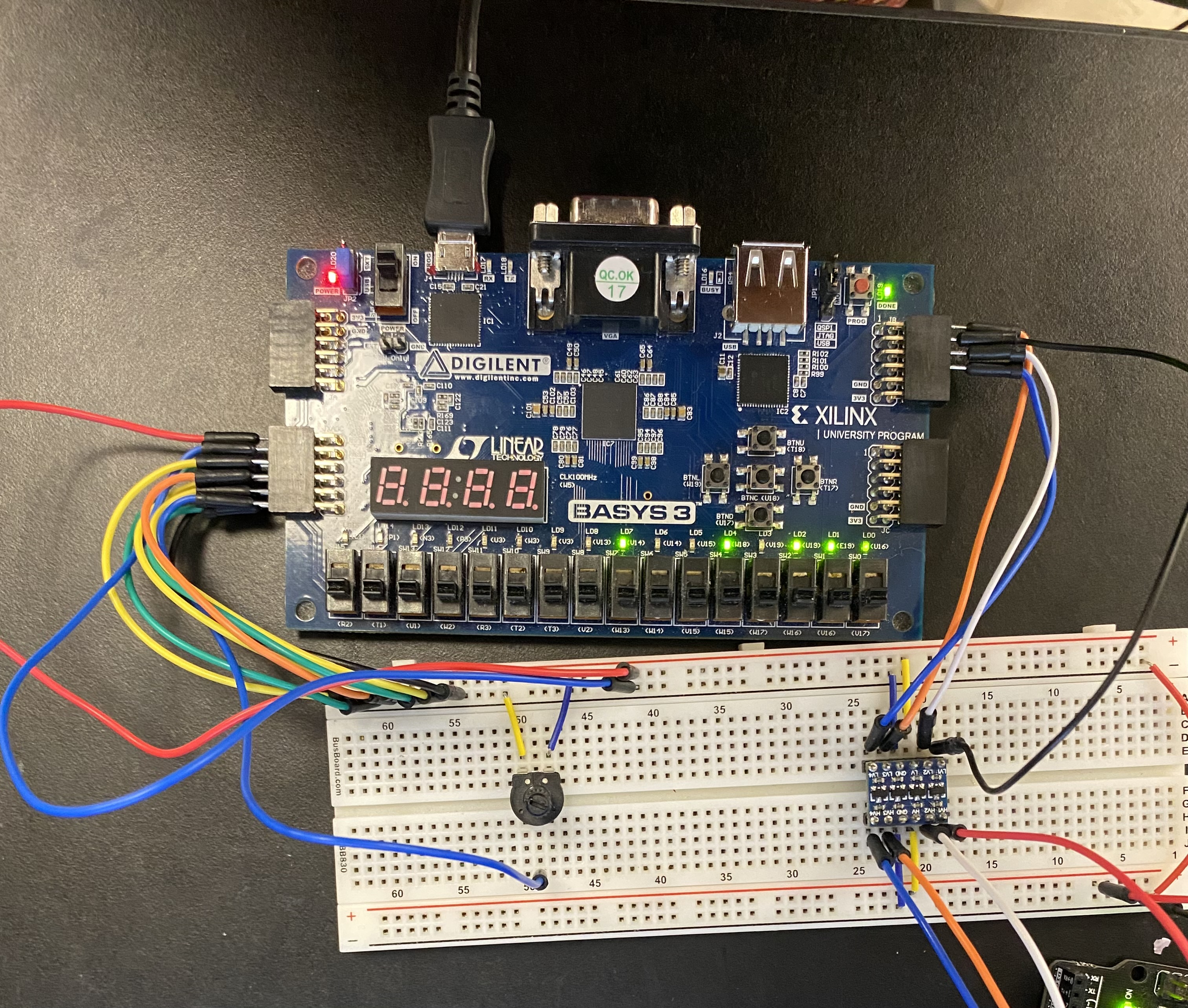
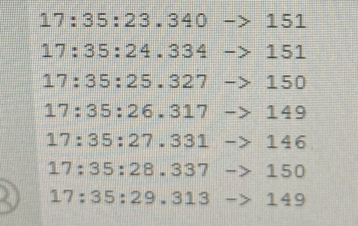
Figure 6. Results for 151 in decimal.
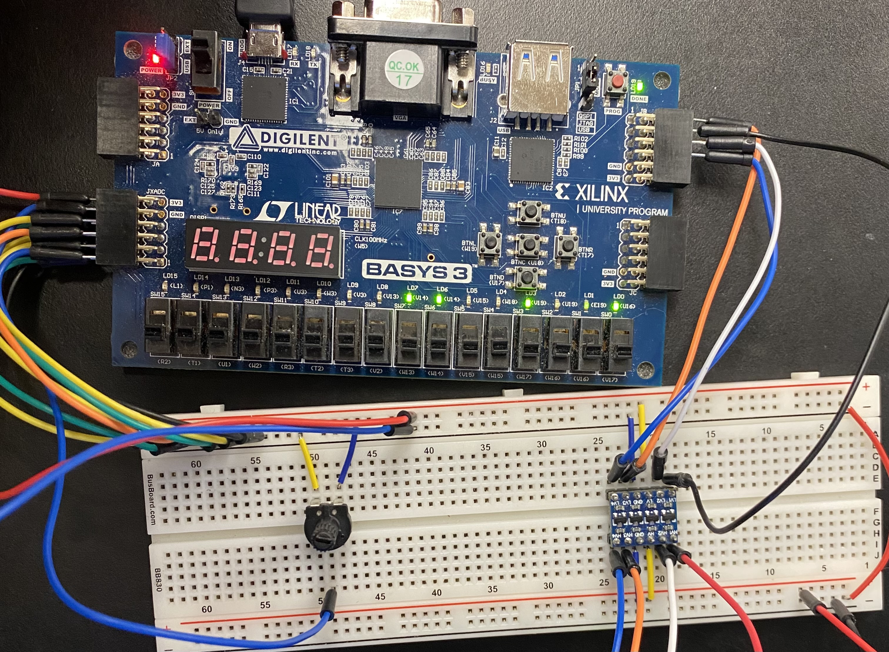
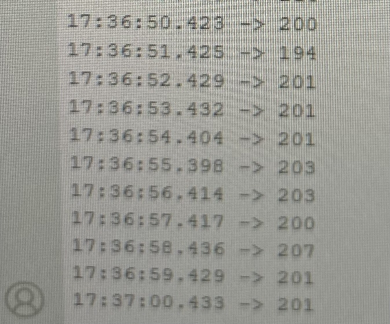
Figure 7. Results for 201 in decimal.
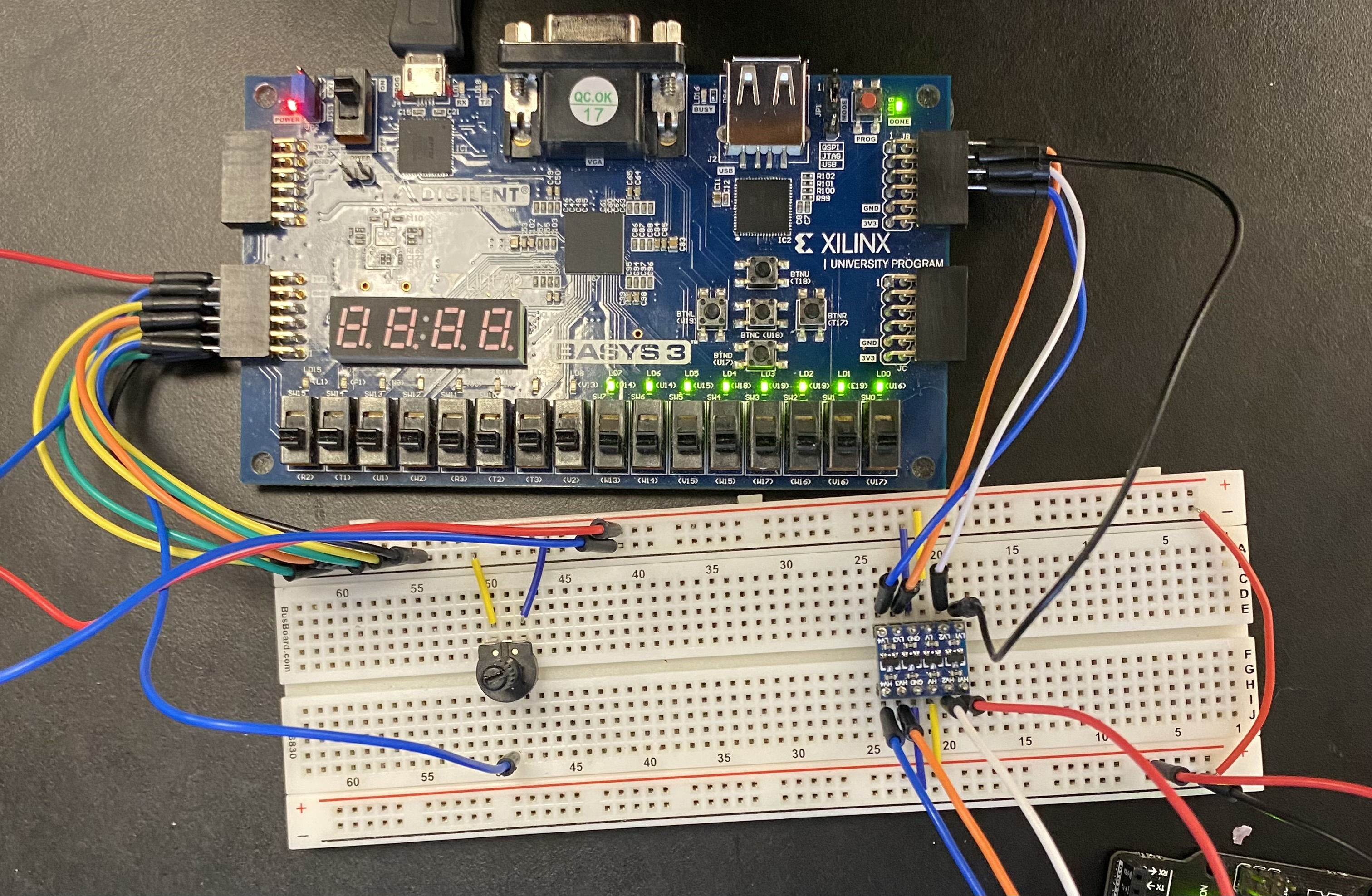
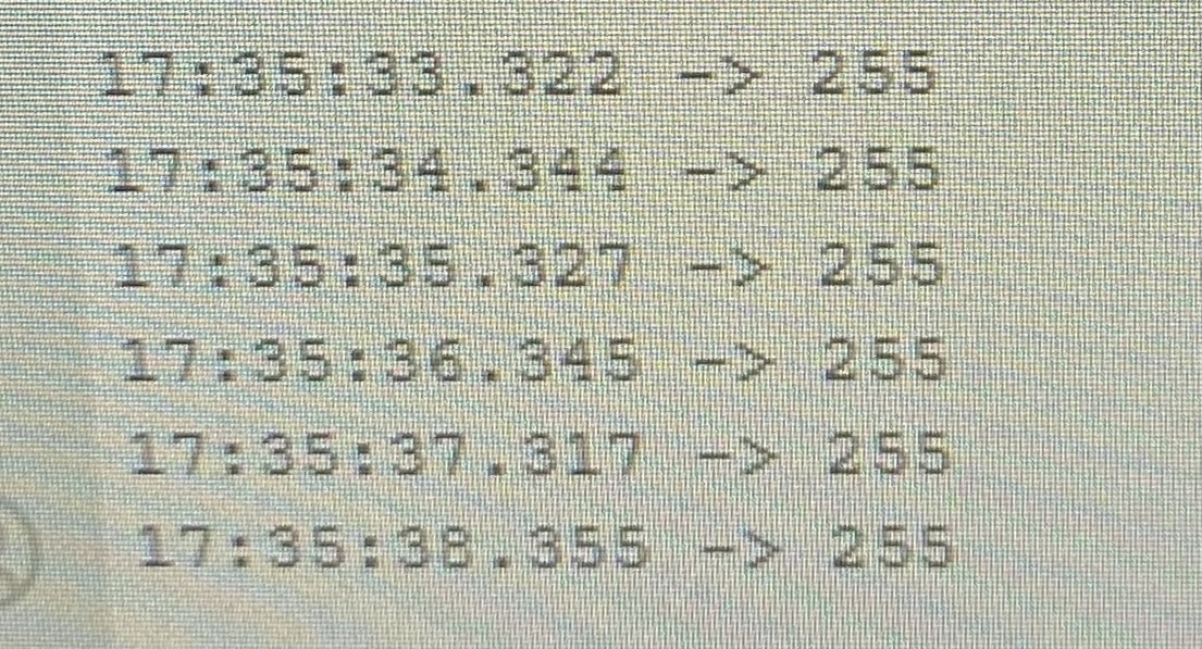
Figure 8. Results for 255 in decimal.