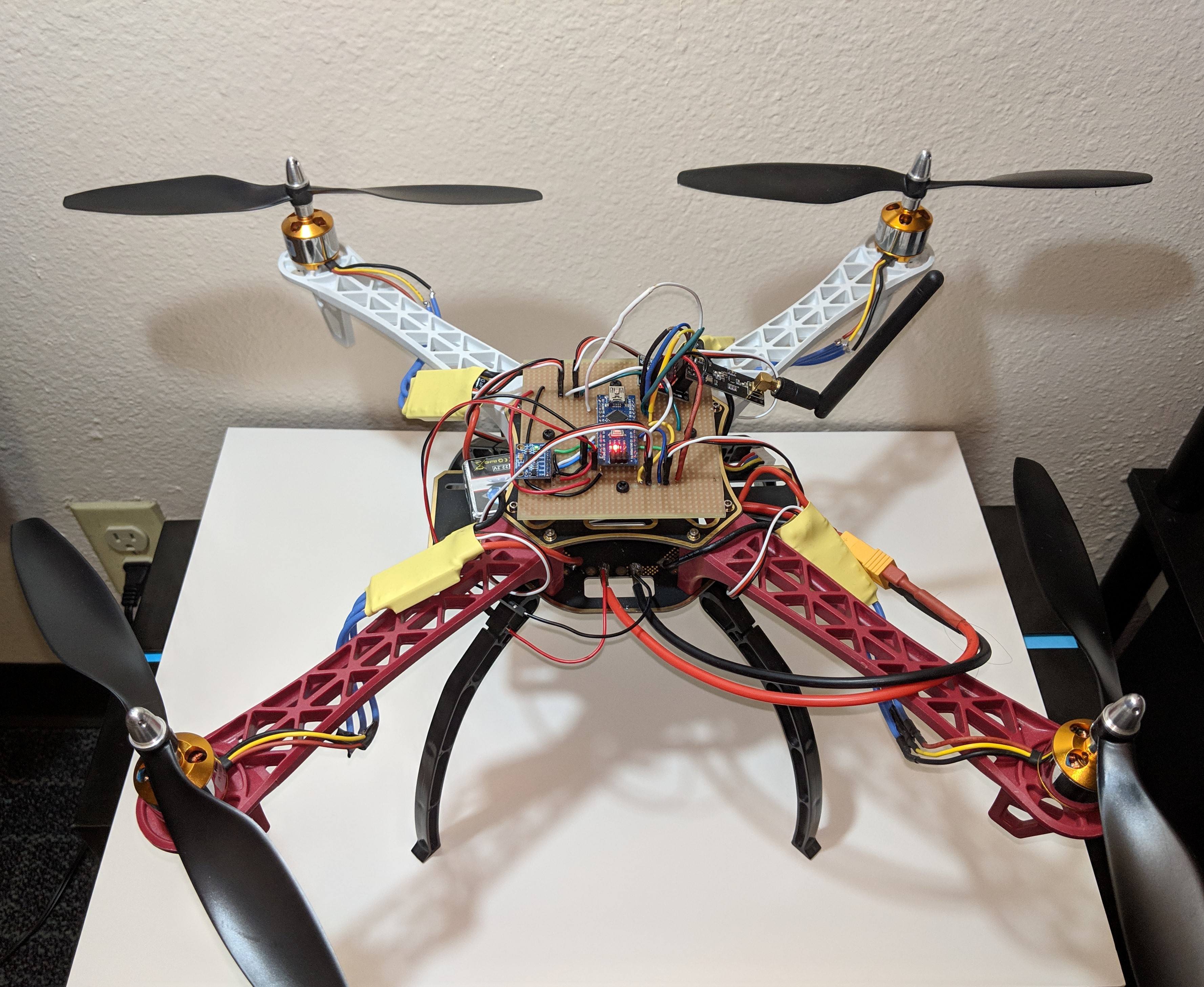
The Arduino Drone: Sean Eaton
This Arduino
drone is based on Nikodem Bartnik's instructables tutorial which can be
found here. Many thanks to Nikodem
for creating his schematics and writing the Arduino code.
Introduction:
This Arduino Drone was
done for
the 1st Fort Lewis College Digital Design contest. Two different
Arduino's are used for the Drone Flight Controller and for the Drone
Pilot Remote. The Arduino Nano was used for the flight controller
because of its small form factor and because it was easily integrated
into my initial design. The Arduino Uno was mainly used because it was
what I had available at the time. The main difference between the
Arduino Nano and Uno is form factor, other than that, they are
identical for the purposes of this project.
Standard drone
parts such as the frame, electronic speed controllers
and motors, and propellers were used in addition to a custom Arduino
powered Flight Controller and Pilot Remote. The standard drone parts
cost less than $120 while the Arduino components and electrical parts
together can cost around $85, less if certain tools and materials are
already available. Expenses for this drone could be as little as $150
if a soldering iron, wires, PCB boards, and cheap Arduino components
are readily available.
This drone could be potentially used for many different applications. A
different kind of frame and some adjustments to the hardware could
allow for the drone able to carry loads, a camera could be mounted to
the drone to capture footage, or sensors could be mounted to collect
data such as temperature, air pressure, humidity, and so on. This drone
also serves as a good learning tool for how drones work.
Materials:
There are three
categories of parts used in this drone. The first is the standard drone
parts that are commonly used in all DIY drone kits. The second are
Arduino components that were used in the drone flight controller and
pilot remote. Lastly there are the standard electrical parts like
wiring and solderable PCB boards which one may have handy prior to this
project.
Figure 1: Table of Drone
Parts Used
| Quantity |
Part |
Price |
| 1 |
450 Drone Frame |
$18.99 |
| 1 |
11.1V 2200 mAh
Lithium
Polymer Battery |
$17.99 |
| 1 |
Lithium Polymer
Battery Balance Charger |
$8.79 |
| 4 |
A2212 1000KV
Brushless Motors |
* $65.99 |
| 4 |
30A Electronic Speed
Controllers |
* $65.99 |
| 4 |
1045 Sized Propellers |
* $65.99 |
* These parts
were sold together
The total for these parts is around $111.76 from Amazon. There may have
been price changes since the parts were first ordered but it should be
around that range. In addition, these parts are also available from
different vendors who sell these parts for less compared to the prices
found on Amazon.
Figure
2: Table of Arduino Parts Used
| Quantity |
Part |
Price |
| 1 |
MPU6050
Gryo & Accelerometer |
$5.39 |
| 3 |
NRF24L01+
2.4 GHz Transceiver |
$13.99 |
| 3 |
Arduino
Nano |
$13.86 |
| 10 |
Joysticks |
$11.99 |
The total for these parts is around $45.23 on Amazon. The MPU6050 Gryo
and Accelerometer is a small board that is easy to wire up to an
Arduino. It is necessary for the proportional-integral-derivative (PID)
controller code. The NRF24L01+ transceivers are the antenna boards
visible on the drone and controller. Arduino Nano's can be purchased in
a pack of 3 which is very useful since two can be used for the flight
controller and pilot remote. The pack of 10 joysticks is the cheapest
option per joystick although only two are only needed.
Figure 3: Table of Electrical
Parts
| Quantity |
Part |
Price |
| 1 |
Soldering
Iron Kit |
$19.99 |
| 1 |
Pack
of Wires |
$16.75 |
| 1 |
Stripboard |
$10.78 |
| 1 |
Set
of Spacer Screws |
$9.99 |
The total for
these parts is around $57.51 on Amazon once again. The stripboard isn't
necessary, any type of solderable PCB board will do. Many of these
components may already be available to someone too which decreases the
total cost of the drone substantially.
Methods:
The Drone Frame:
The drone frame is easily constructed and the kit will contain all the
necessary screws. An allen wrench or hex key is needed to fasten the
screws correctly or a flat head screwdriver can also work.
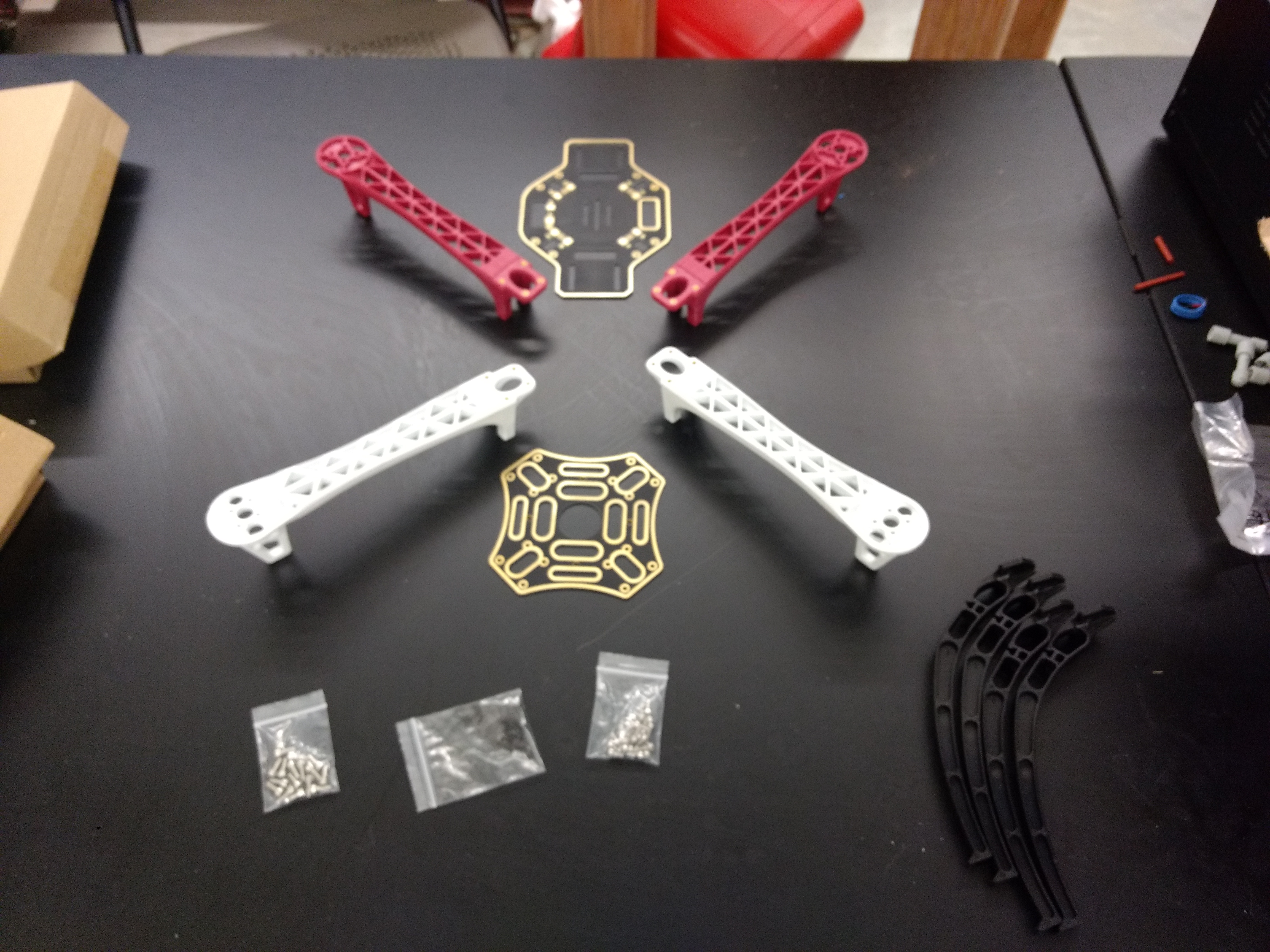
Figure 4:
450 Drone Frame parts laid out
Keep in mind that the electronic speed controllers (ESCs) must connect
to each brushless motor and be soldered to the built in power
distribution board of the frame. The power distribution board is the
uppermost board in the picture above. The connections are also shown
below. This process has to be repeated four times for each of the
frame's four legs.
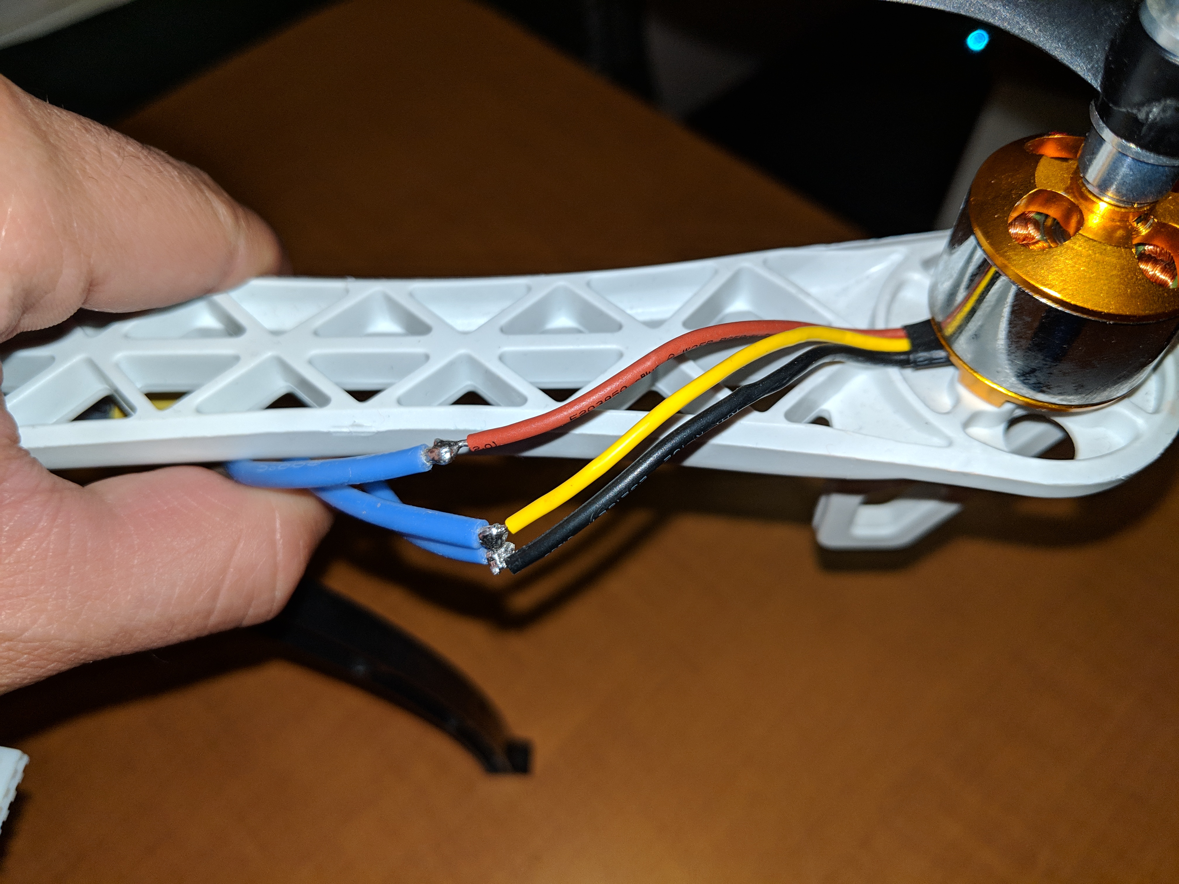
Figure 5: Motor to ESC
connections
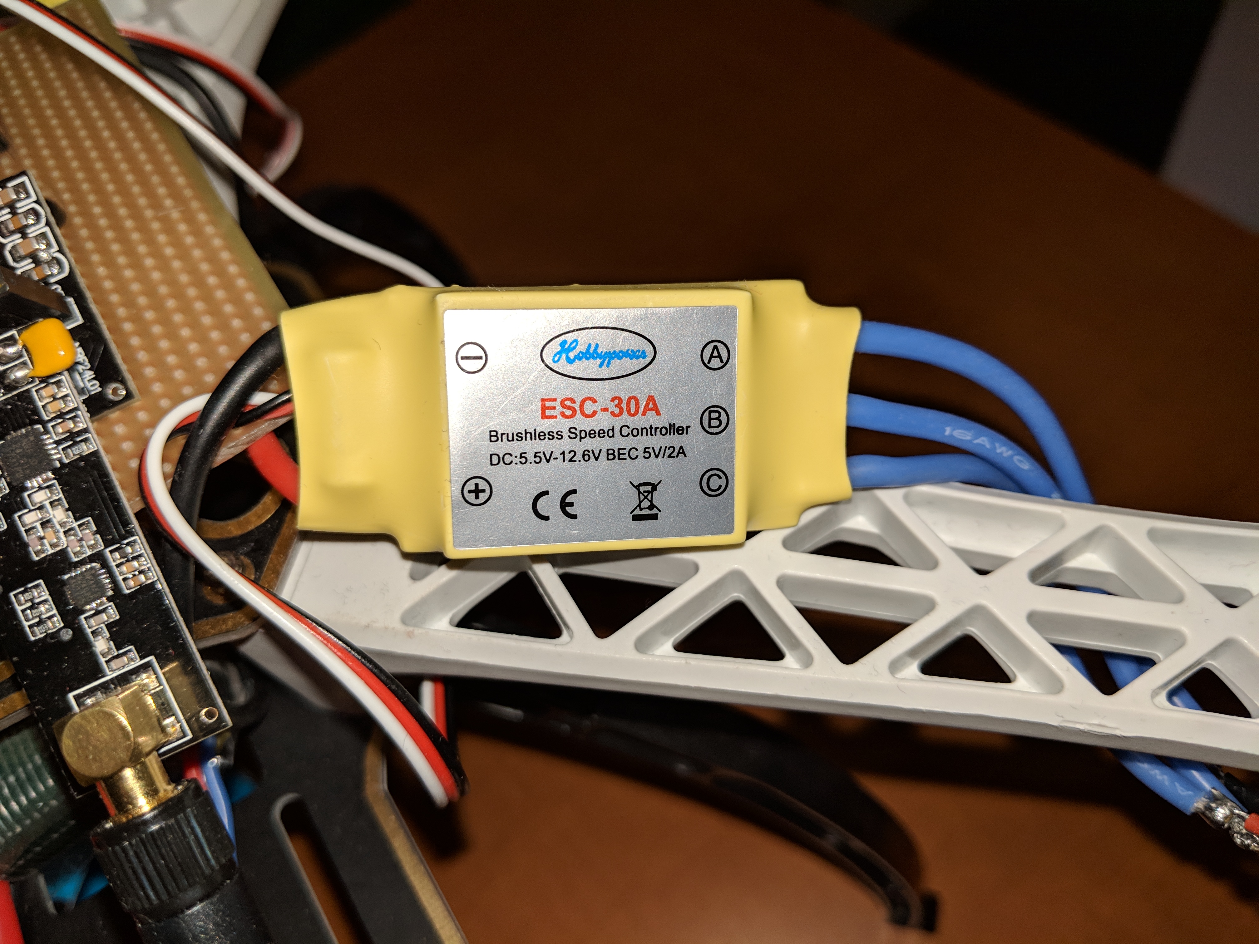
Figure 6:
ESC on the frame
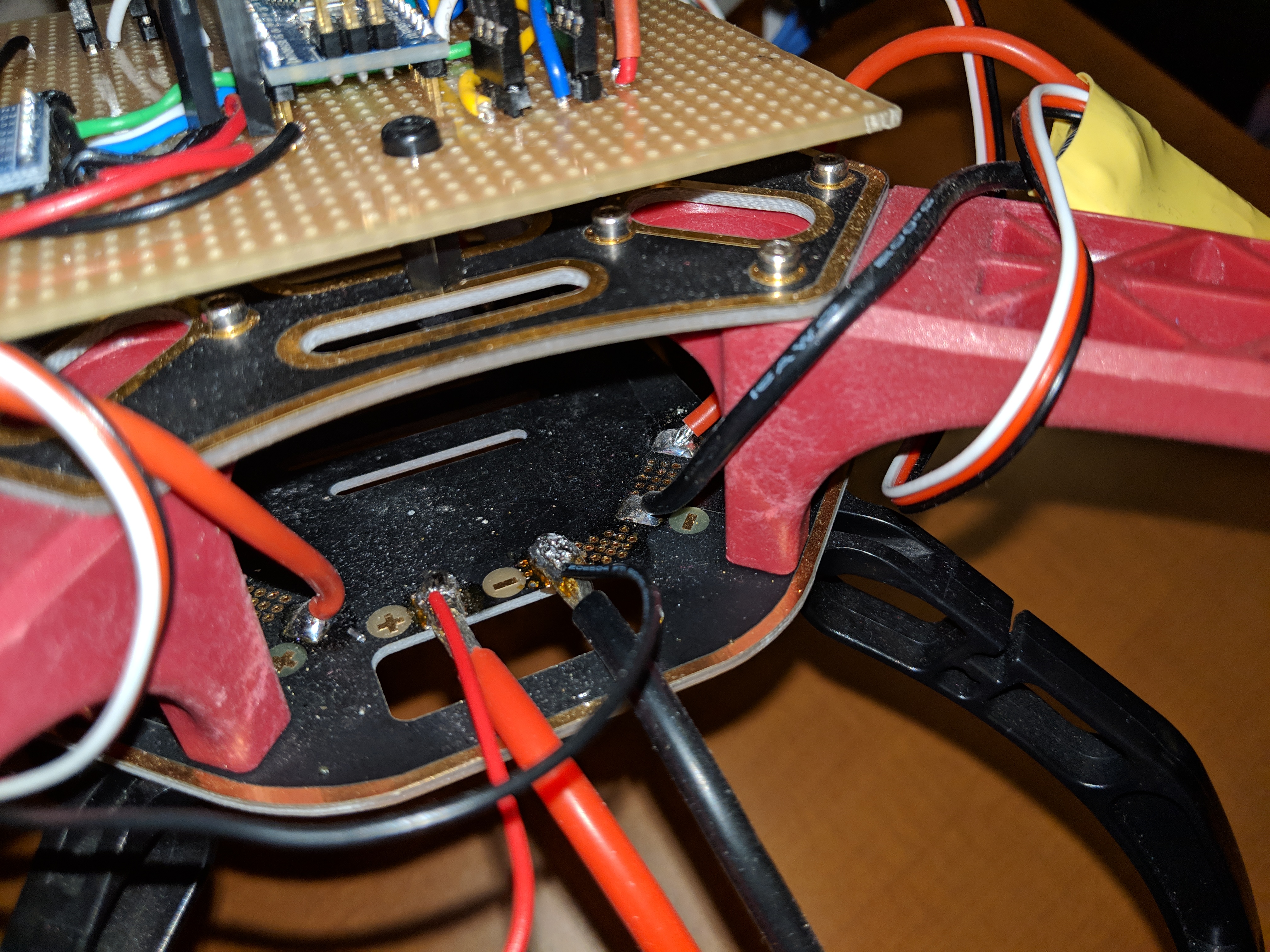
Figure 7: ESC
connection to power distribution board on the frame
The Flight
Controller: The flight controller has a somewhat easy set
up. The main components to be wired up are the MPU6050, NRF24L01+, the
Arduino Nano, and header pins for the ESCs. I used a strip board
because it made wiring easier for me but any type of solderable PCB
board can be used.
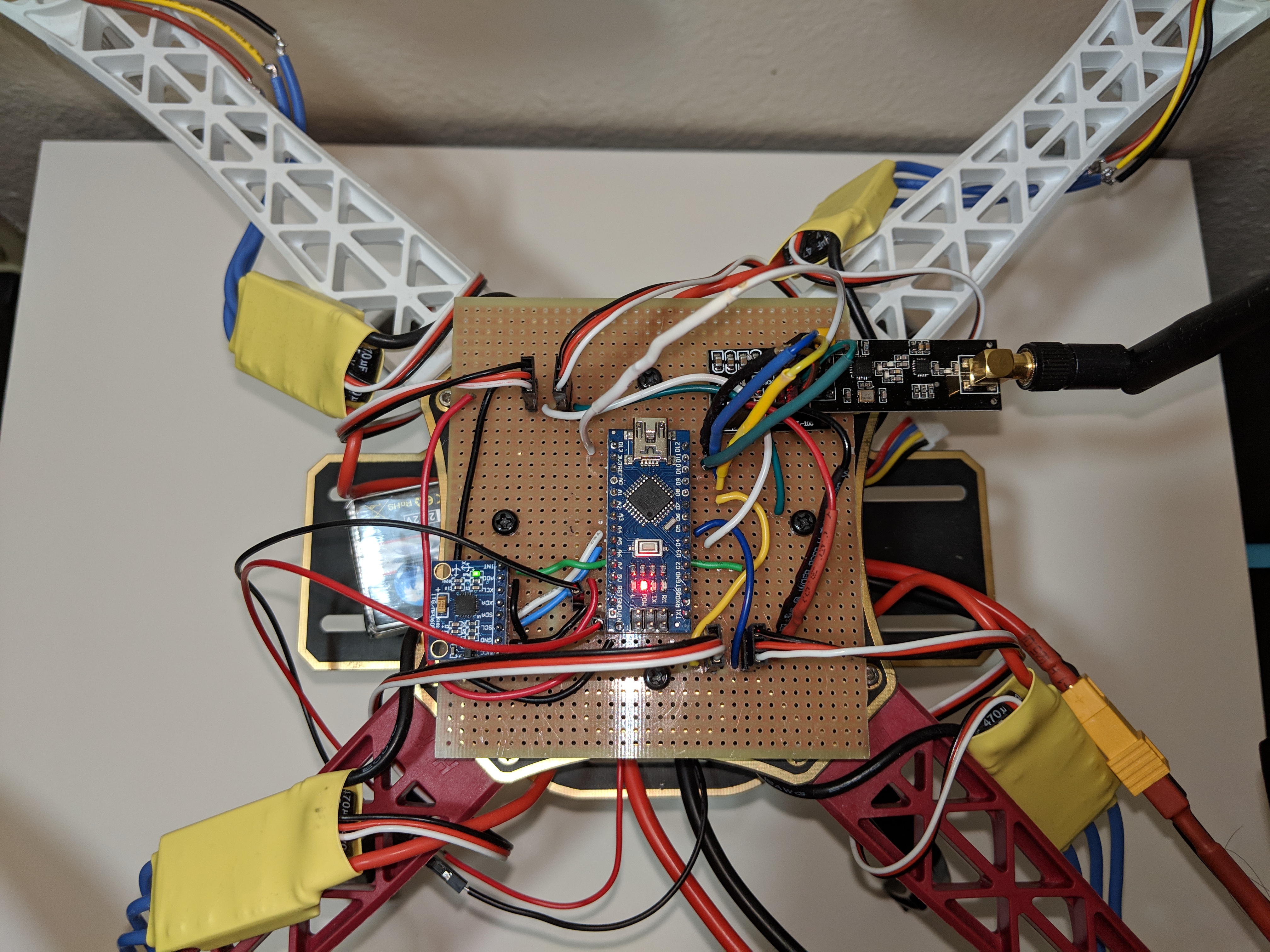
Figure 8: On board
flight controller
The following schematic was used as a guide. This was the schematic
Nikodem Bartnik uploaded to his instructables page.
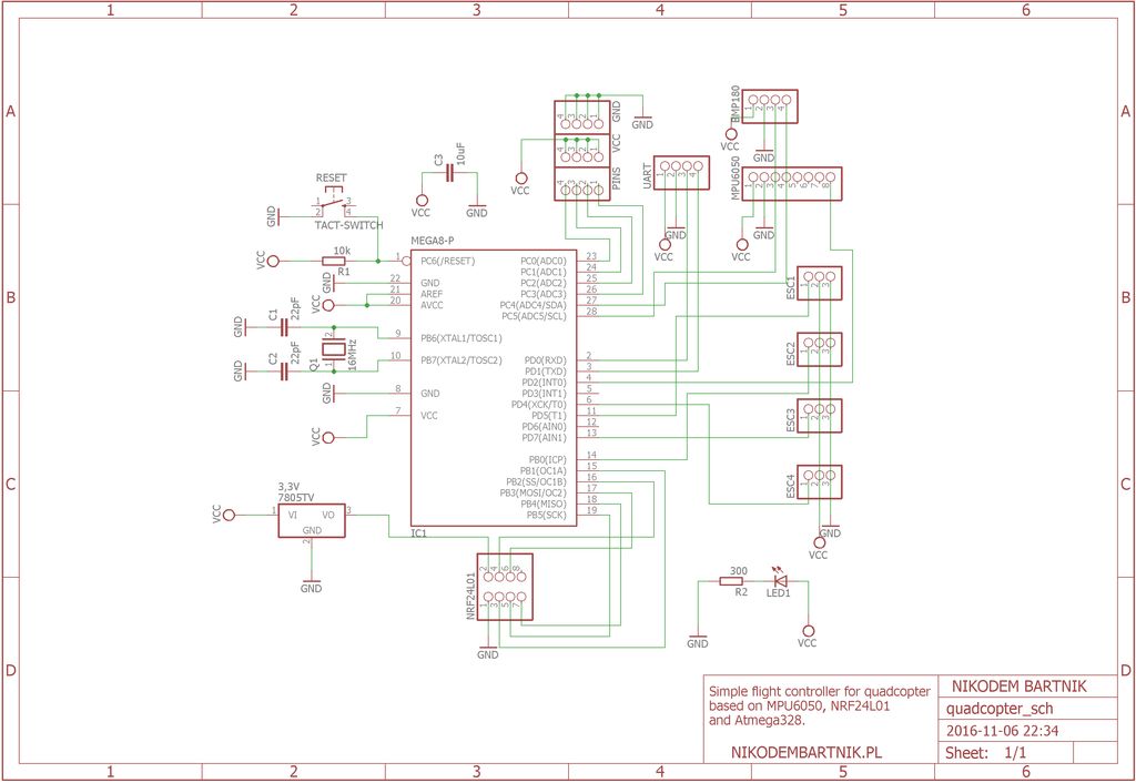
Figure 9: Flight
controller schematic by Nikodem Bartnik
Some things were omitted because I was using the Arduino Nano instead
of the Atmega328 chip by itself. These were things like the linear
voltage regulator, capacitors, and the 16 MHz crystal oscillator since
the Arduino Nano already had those things handled. The Atmega328 pins
correspond to the pins of the Arduino Nano (and Uno). With the help of
this pinout diagram I was able to figure out the equivalent connections
for the different components on the flight controller.
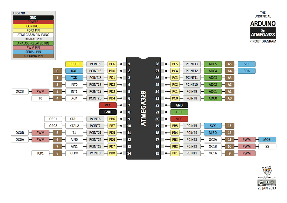
Figure 10: Atmega328
pinout and equivalent Arduino Pins
The Pilot Remote:
The pilot remote is very simple compared to the flight controller. The
wiring for the NRF24L01+ is identical to the flight controller and the
only other components are the two joysticks. Nikodem Bartnik's
schematic was again used for this with similar minor adjustments as
well as aided by the previous pinout diagram.
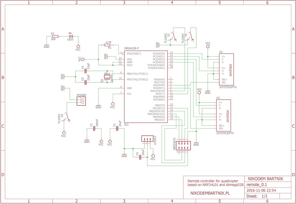
Figure 11: Drone pilot
remote schematic by Nikodem Bartnik
The pilot remote is very rough right now. It's main purpose was for
testing and the green PCB board is unnecessary right now. The main
challenge with the pilot remote was wiring the joysticks correctly. The
pins for the joy sticks are on the left side which is why they are
floating right now. They can be reworked to fit on a single board but
different joysticks would be required or some easy method of detaching
the joystick from the PCB.
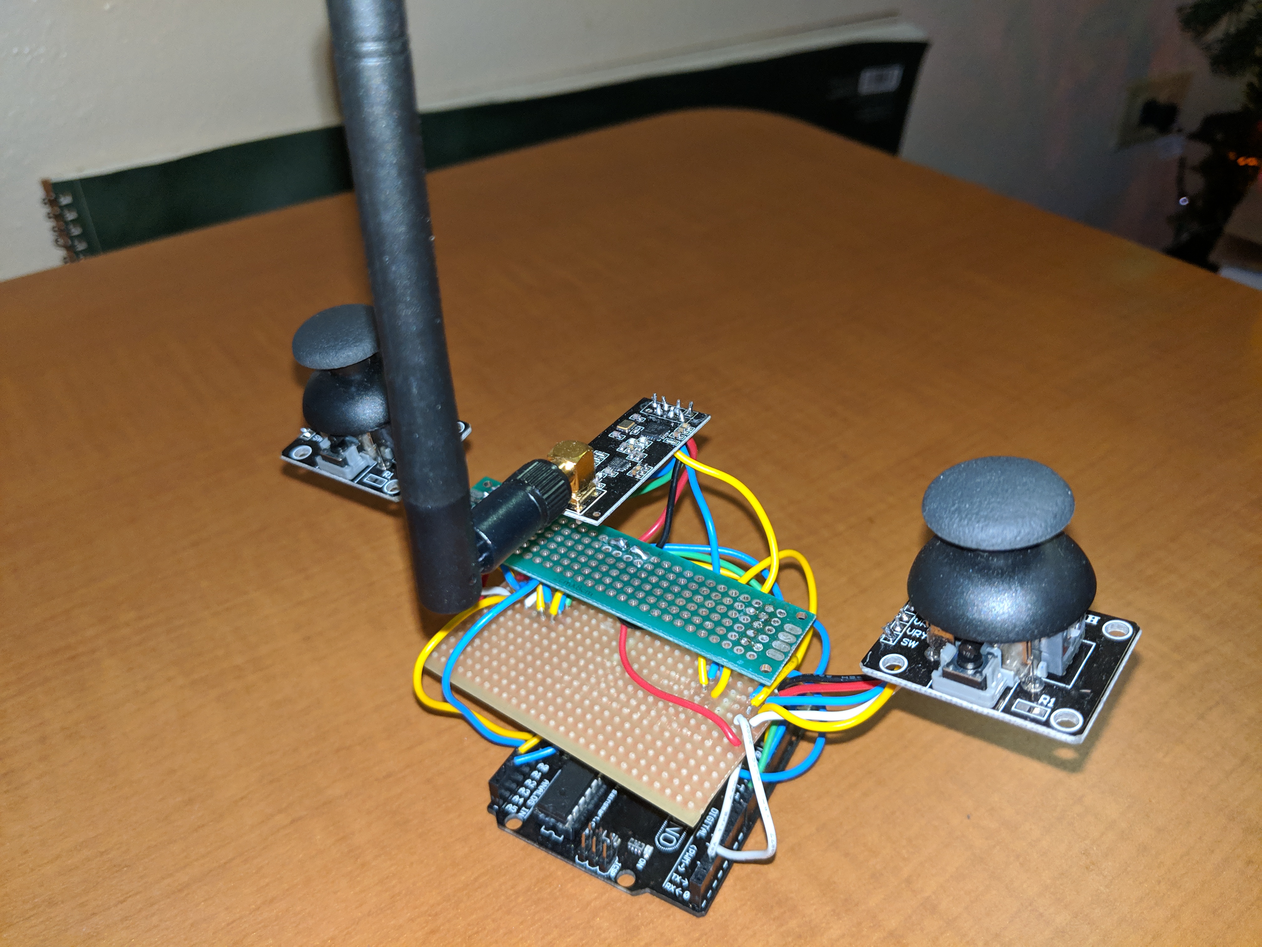
Figure 12: Drone pilot remote
Results:
I initially built the
flight controller by following Nikodem Bartnik's schematic as closely
as I could. This meant I had to use the Atmega328 microcontroller by
itself and order the 16 MHz crystal oscillators, capacitors, and linear
voltage regulators. Unfortanely the flight controller wasn't
functional. This first version of the flight controller is shown below:
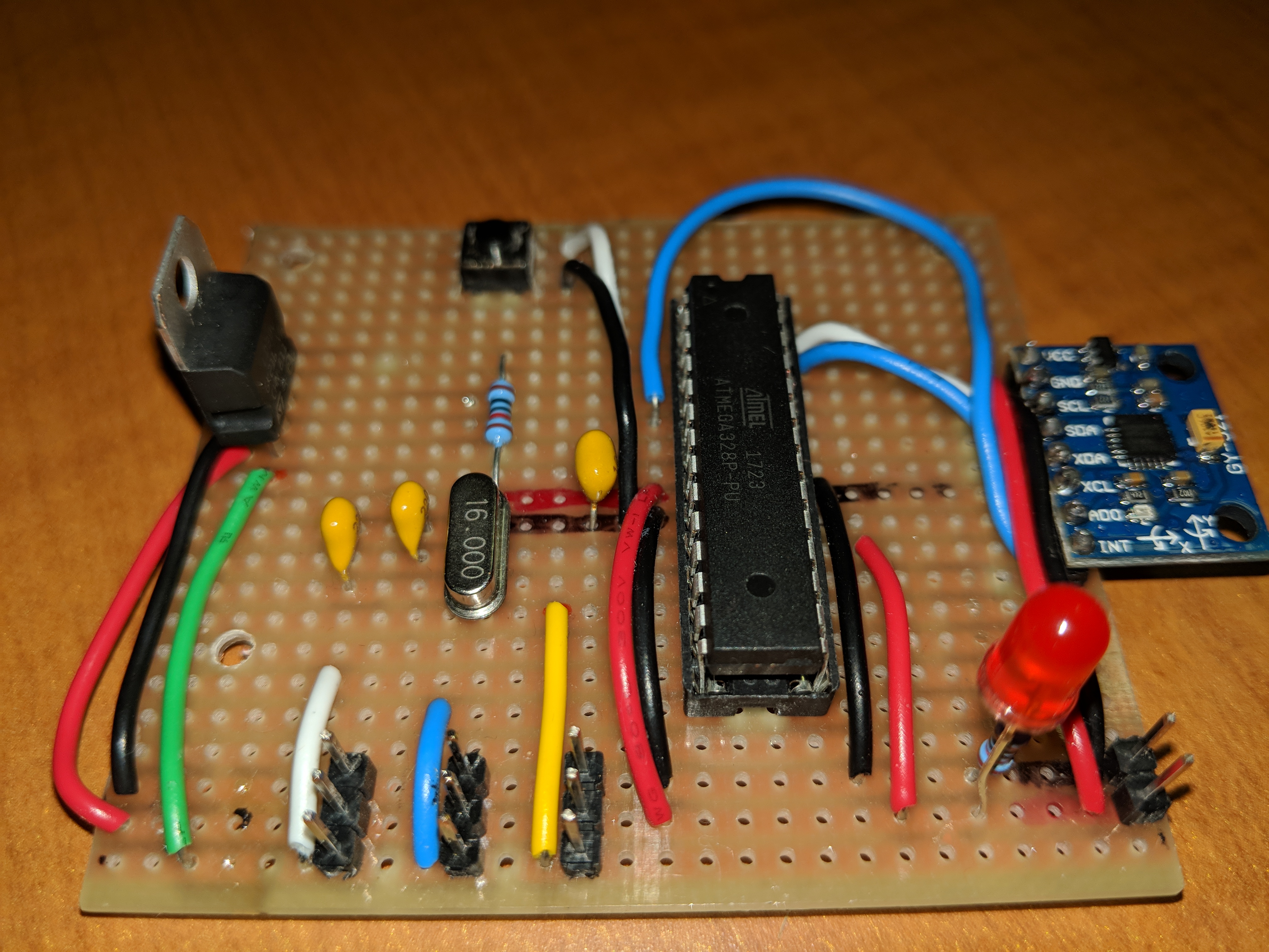
Figure 13: Flight
Controller 1.0
The linear voltage regulator is the black part with the silver
protrusion on the left side of the board. The Atmega328 microcontroller
is the large black rectangle. The blue board on the right side of the
board is the MPU6050. The yellow blobs are ceramic capacitors and the
silver component between them is the crystal oscillator.
The Atmega328 microcontroller is actually the same
microcontroller used on the Arduino Uno. This can be seen in Figure 14
which also shows a comparison of the sizes of these two boards. The
major advantage gained from building the flight controller this way is
that the size of the flight controller can be cut down signficantly. A
separate Arduino Uno is not required and mounting and stabilizing the
MPU6050 is taken care of easily. The major disadvantage to this is the
loss of the USB port which can be used for debugging. The code for the
Atmega328 is written using the Arduino IDE (Integrated Development
Environment). The Arduino IDE has a useful tool called the serial
monitor which can be used to debug issues by displaying messages to the
user. Since Flight Controller 1.0 was not functional and I couldn't use
the serial monitor to identify any issues I decided that it would be
simpler to use an Arduino Nano.
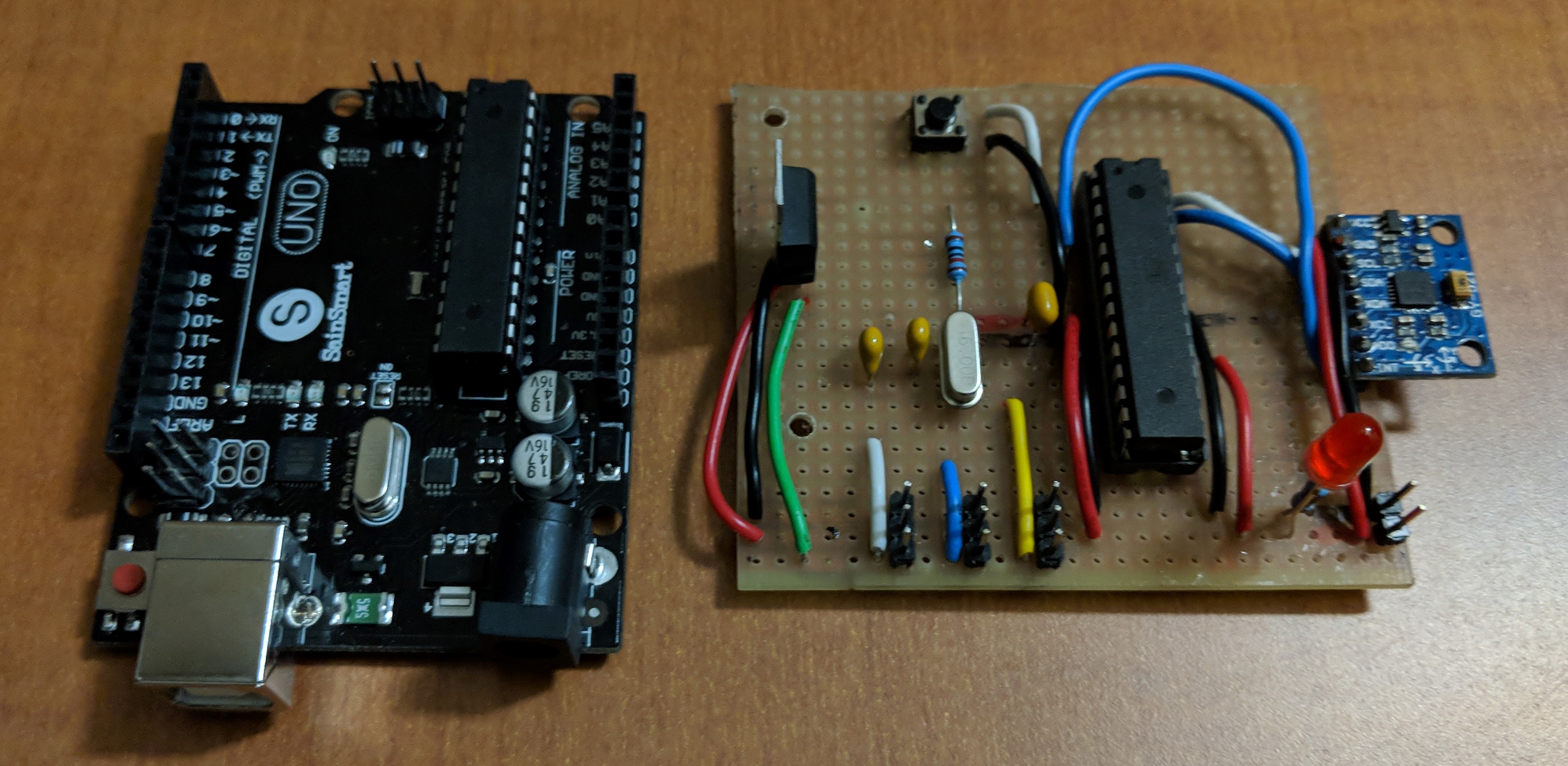
Figure 14: Arduino Uno
compared to Flight Controller 1.0
The Arduino Nano was chosen for its small form factor and most
importantly because it is nearly identical to an Uno in functionality.
The microcontroller used on the Arduino Nano is the Atmega328P which is
the small black square seen on the Arduino Nano in Figure 15. There are
minimal differences in the functionality of the Atmega328 and
Atmega328P such as the two additional analog inputs. All that had to be
done to get the code working on the Nano was changing the settings in
the Arduino IDE to upload to the Nano.
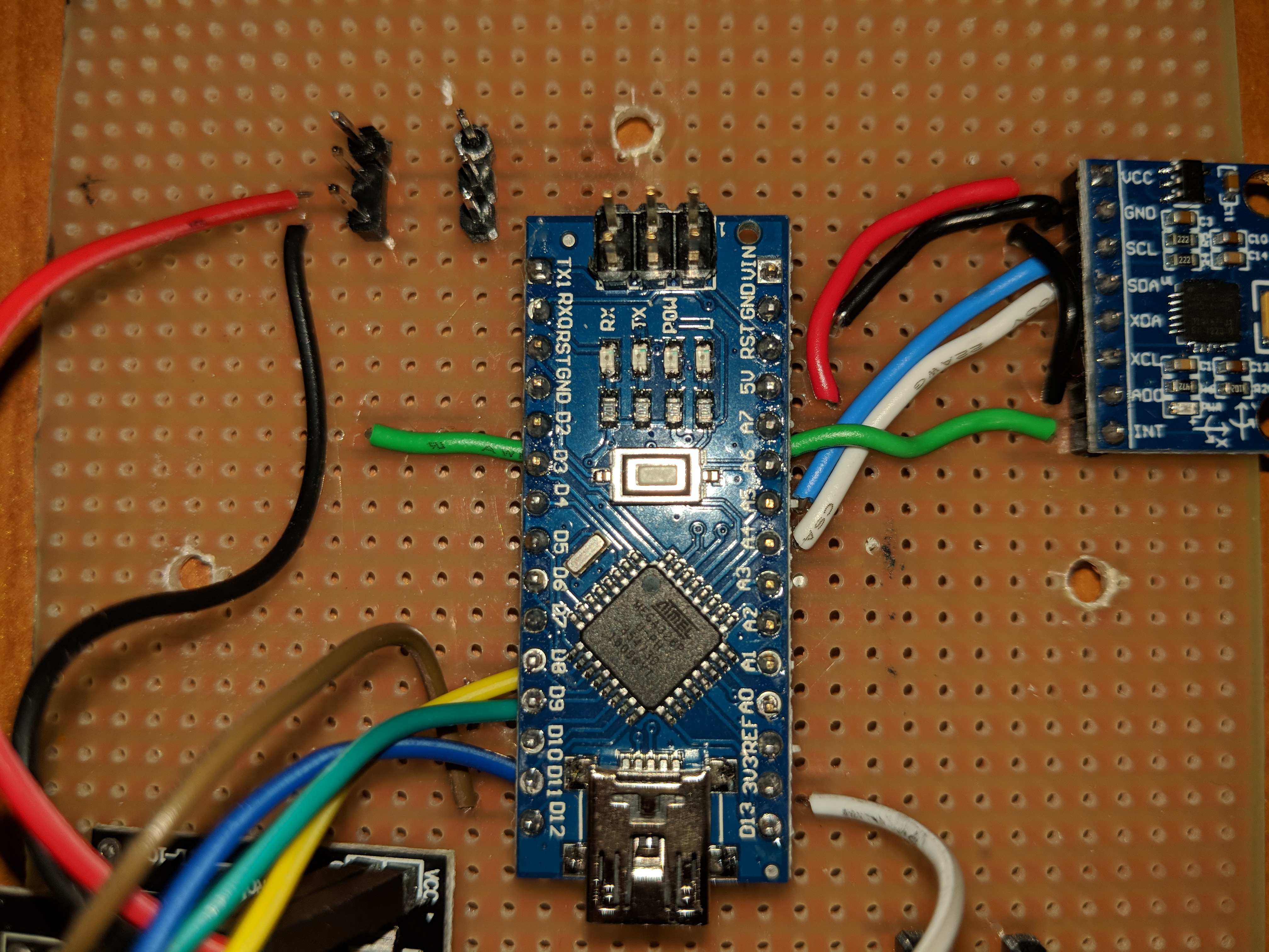
Figure 15: Arduino Nano
on Flight Controller 2.0
Using the pinout diagram shown in Figure 10, Flight Controller 2.0 was
built. Flight Controller 2.0 is larger than the Arduino Uno and Flight
Controller 1.0 but it is very simplified and functional. The sides
could even be trimmed down further or a different layout could decrease
the size of the board as well. Figure 16 shows a size comparison of the
different boards.
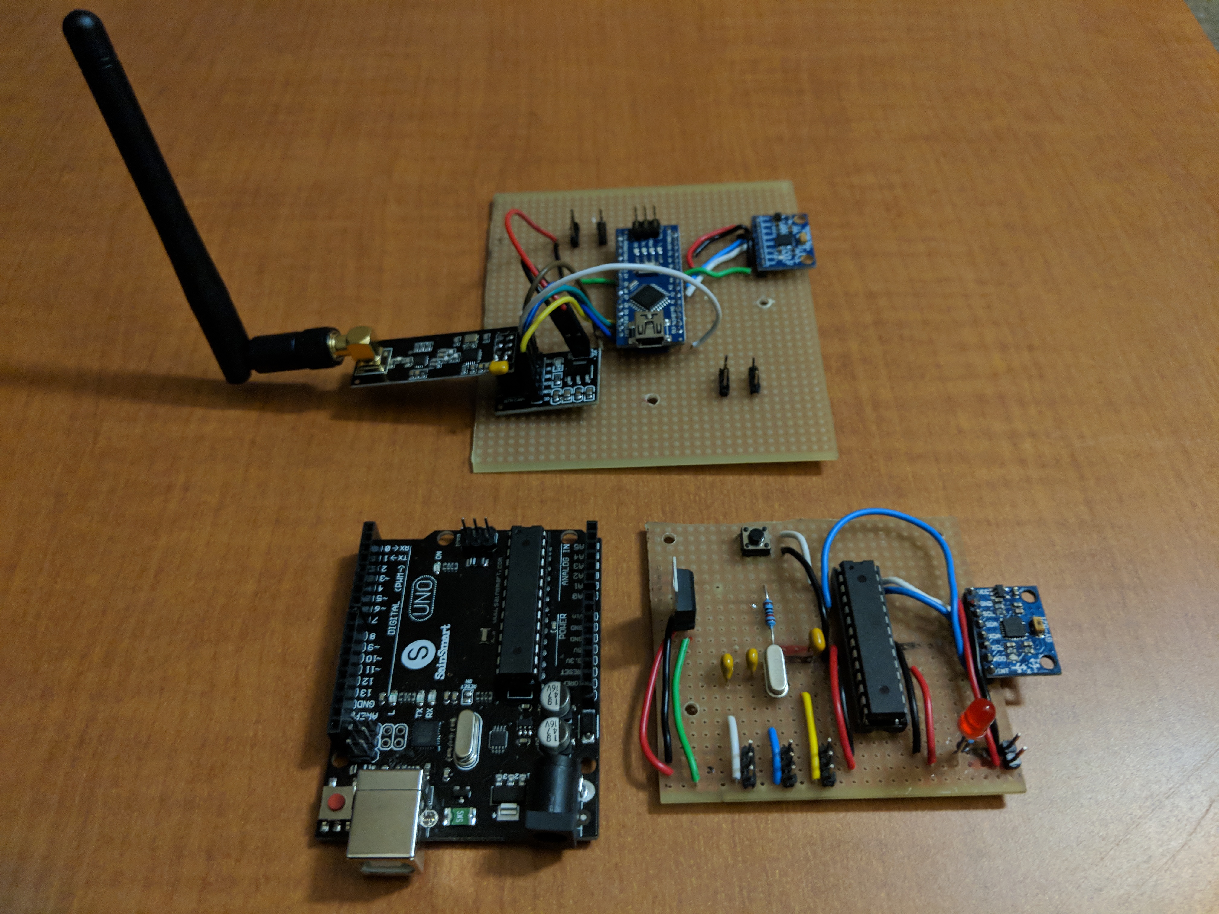
Figure 16: Comparisons
between Flight Controller 2.0 (top), Arduino Uno (left), and Flight
Controller 1.0 (right)
The Arduino Nano gets powered by drone's 11.1V lithium polymer battery.
Using the 5V pin on the Arduino Nano a 5V rail is used to supply power
to the MPU6050 and NRF24L01+ in addition to the ESC pin headers. The
MPU6050 has SCL and SDA pins that must connect to the designated SCL
and SDA pins on the Arduino. SCL is the clock line while SDA is the
data line and this connection is necessary for the MPU6050 to function
correctly. The NRF24L01+ has similar requirements where the SCK (serial
clock), MOSI (Master Out Slave In), and MISO (Master In Slave Out) must
be correctly connected. These pins are necessary for the transceiver
and Arduino to communicate. The ESC pin headers are connected to 5V and
ground as well as an additional pin that connects to a digital pin on
the Arduino.
The pilot remote (Figure 12) hasn't been modified yet since I first
began testing. The current design is not ideal at all. The necessary
pins for the joysticks are power, ground, VRX, VRY, and SW. VRX and VRY
tell the Arduino how the joystick is positioned in X and Y directions
while SW lets the Arduino know if the joystick has been pressed down
like a button. Analog pins are used for VRX and VRY and a digital pin
is used for SW. The breakout boards of the joysticks have the pins on
the left side only which prevented me from soldering the joysticks to a
board directly. Figure 17 shows this and the connections for the
transceiver.
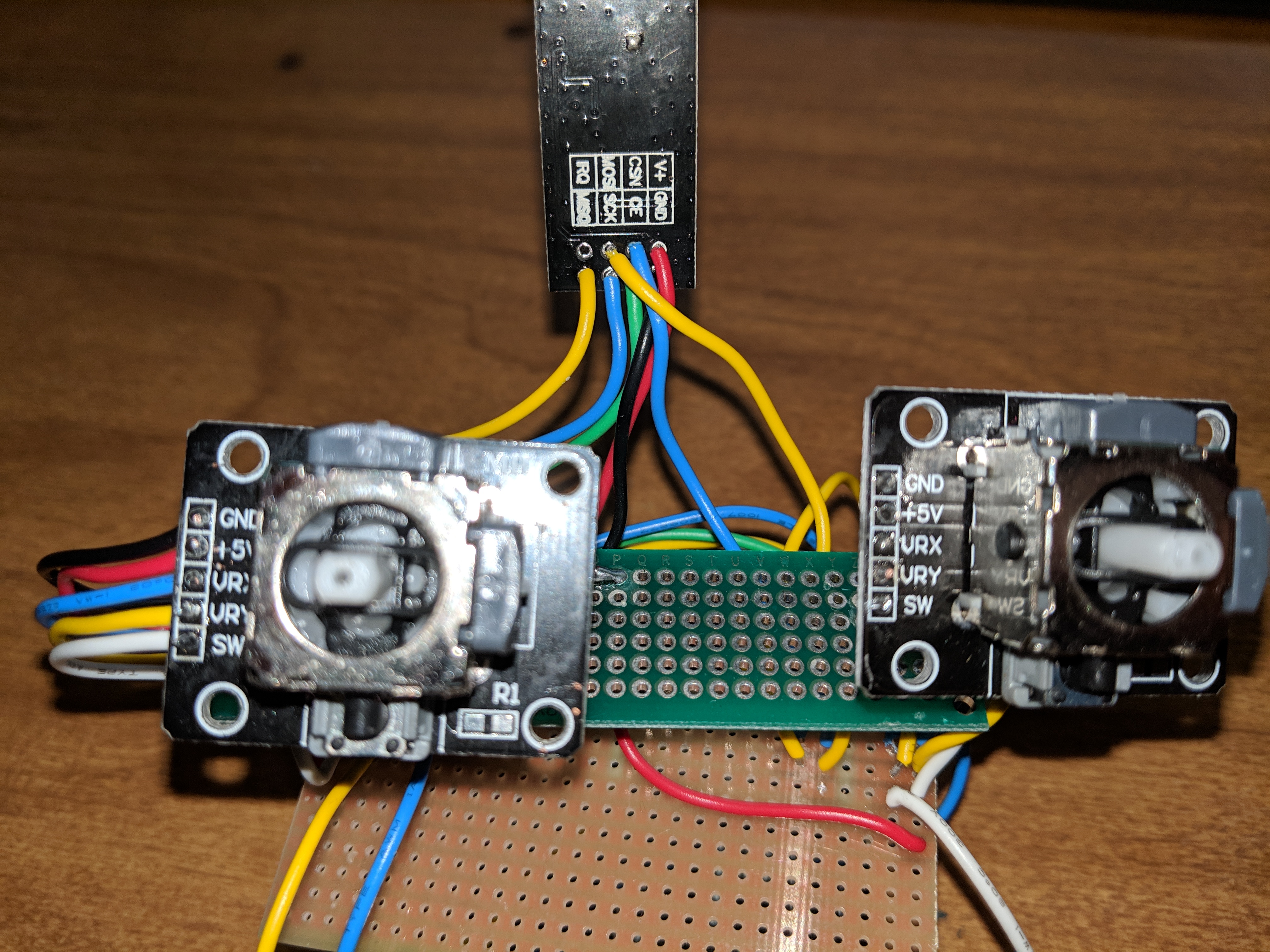
Figure 17: Pilot remote
joysticks and transceiver
Discussion:
The drone has not flown
yet due to an issue with getting the pilot remote to control the drone
consistently. You may have noticed that the NRF24L01+ transceiver is
set up differently on the flight controller (Figure 8 and Figure 16)
compared to the pilot remote (Figure 12). I am currently experimenting
with
using an adapter to fix this problem which is the major challenge I am
facing right now. I was
able to get the pilot remote to control the drone's motors only once.
This is shown below:
I researched how
other people were using the NRF24L01+ tranceivers and it appears that
the issue is
likely power related. The transceivers are probably experiencing power
fluctuations significant enough to break
communication. The transceiver can only handle 3.3V as a power source
and Nikodem Bartnik indicated in his pilot remote schematic that a 10uF
capacitor should connect the transceiver's ground and power to prevent
power fluctuations which is what others suggested too. People had
success with the adapter board so I ordered those and experimented with
what works best. After testing the transceivers with breakout boards
and 10uF capacitors, I know that using the breakout board in addition
to the capacitor works but now positioning is an issue. I was able to
get the transcievers to communicate consistently for a while
but after moving them I wasn't able to get the same results. During
testing I used the serial monitor in the Arduino IDE and took
screenshots of the results (Figure 18 and Figure 19).
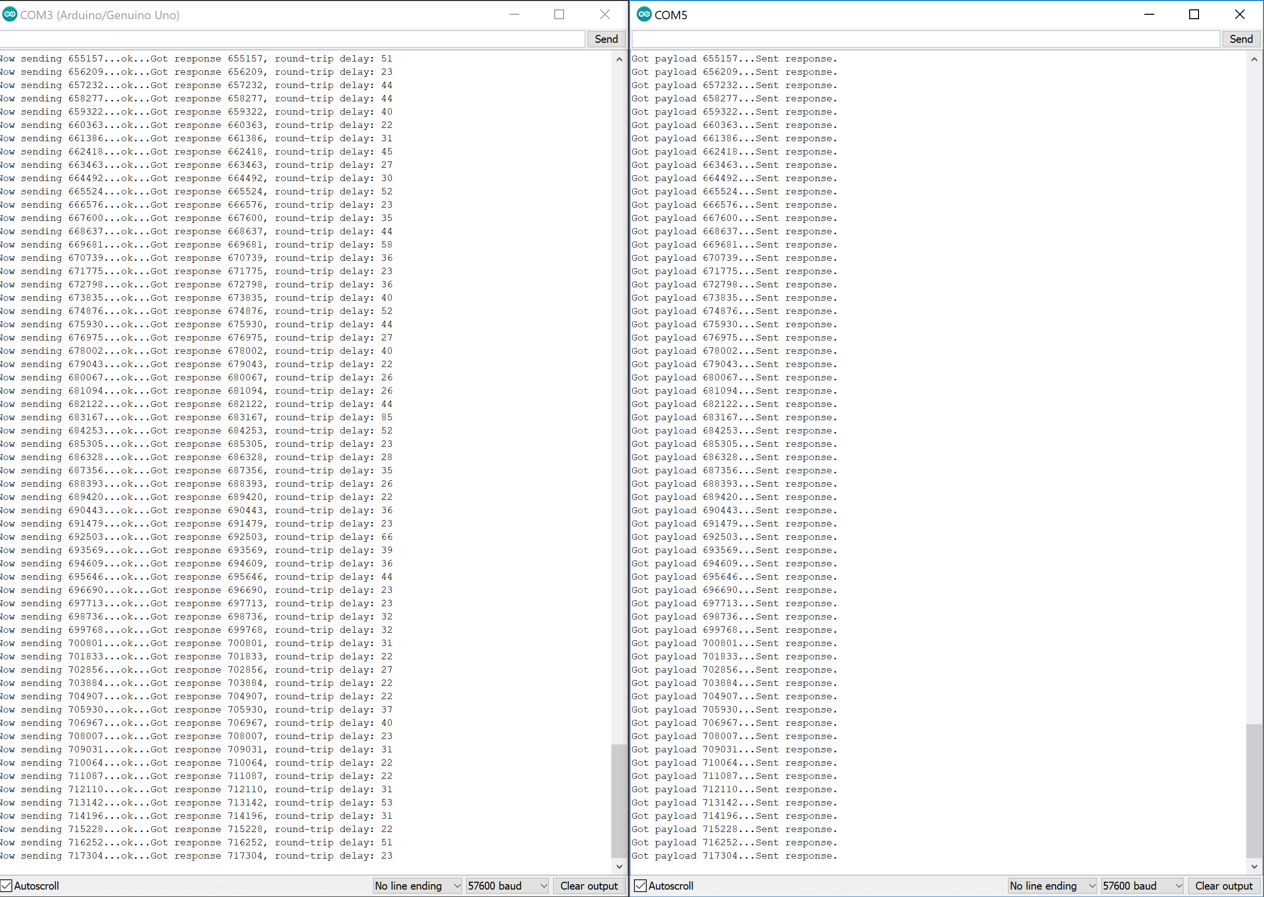
Figure 18: shows
consistent communication between the transceivers
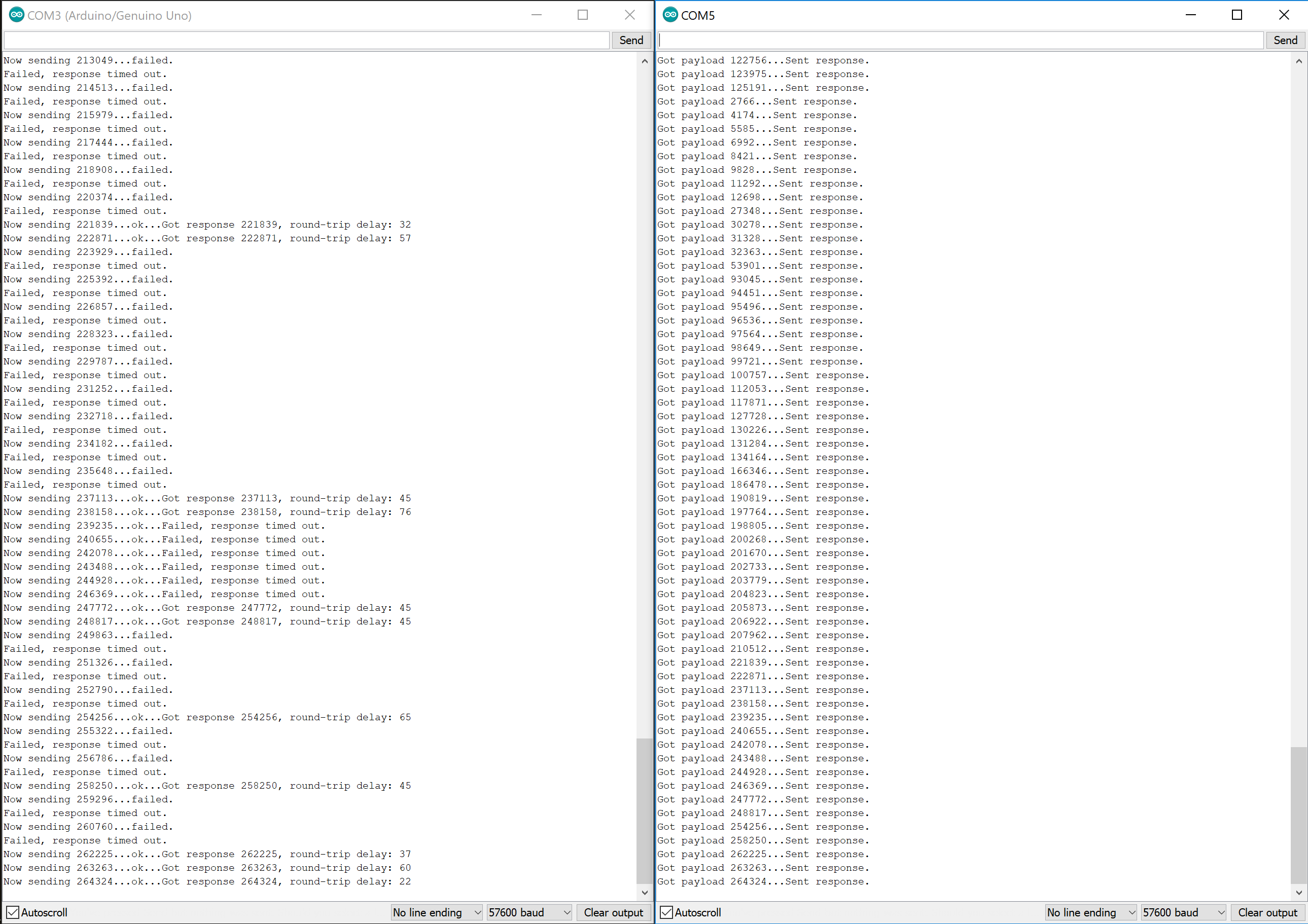
Figure 19:
shows inconsistent communication between the transceivers
In Figure 18 and Figure 19 the number of milliseconds since the
transmitting Arduino is turned on is sent using the transceiver. The
receiving Arduino then receives this payload and sends a response back.
There is successful communication between them when the transmitting
Arduino is able to receive the response. Figure 18 shows the results of
positioning the adapters in just the right way to maintain good
communications between them. In Figure 19 the positioning was changed
and the transmitting Arduino isn't able to detect a response a lot of
the time. The challenge is figuring out how to attach and position the
transciever on the flight controller because it is not able to be
soldered onto the board like the MPU6050 or Arduino Nano because of its
design.
Moving forward, there is one other transceiver adapter board that is
different from the one I am currently using that I may try. This other
adapter doesn't have a 3.3V regulator but it can be easily soldered to
a PCB board and can maintain a steady position easier than the current
adapter.
I
also need to update the pilot remote (Figure 12). The green PCB board
is unnecessary right now and I want to use an Arduino Nano instead of
the Uno. I kept this version of the remote around because of it was the
only one able to communicate with the drone so far. The joysticks can
also use some pin headers so I can solder the joysticks to a PCB board
instead of allowing them to hang in mid air.