CE351 - Microcontrollers 2022 Spring
Maze Solver Robot Project
Sean Eaton
smeaton@fortlewis.edu
Maze Solver Robot Project
Introduction
The Pololu 3pi+ Robot
is a ready to use robot that integrates a variety of sensors into one
PCB. Included on the PCB are two bump sensors, five IR sensors, and a
three axis gyro, accelerometer, and compass. It is also powered by an
ATmega32U4 microcontroller which is easily programmable using the
Arduino IDE. The goal of this project was to understand the Pololu maze
solving example code as well as the robot PCB in order to replicate its
functionality. Previously Pololu offered a different version of this
robot, the 3pi Robot,
which differs from the updated 3pi+ in its sensors as well as the
libraries provided. The original 3pi robot does not include the 3pi+
sensors aside from the IR sensors but it did provide documentation on
its maze solving example code. Using this documentation the example
code was updated to use the newer libraries and was tested on the 3pi+
robot. After this a PCB was designed that replicates the maze solving
functionality of the 3pi+ robot.
Pololu 3pi+ Robot Overview
Below are some images showing
the hardware included on the 3pi+ robot. In the overhead view the 3
axis gyro, accelerometer, and compass can be seen as well as the
LCD, bump sensors, and other various buttons. In the under view
the IR line sensors can be seen along with the motors.
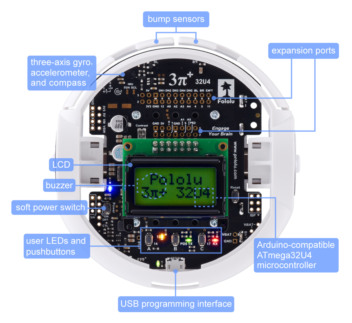
Figure 1. Overhead view of the 3pi+ robot.
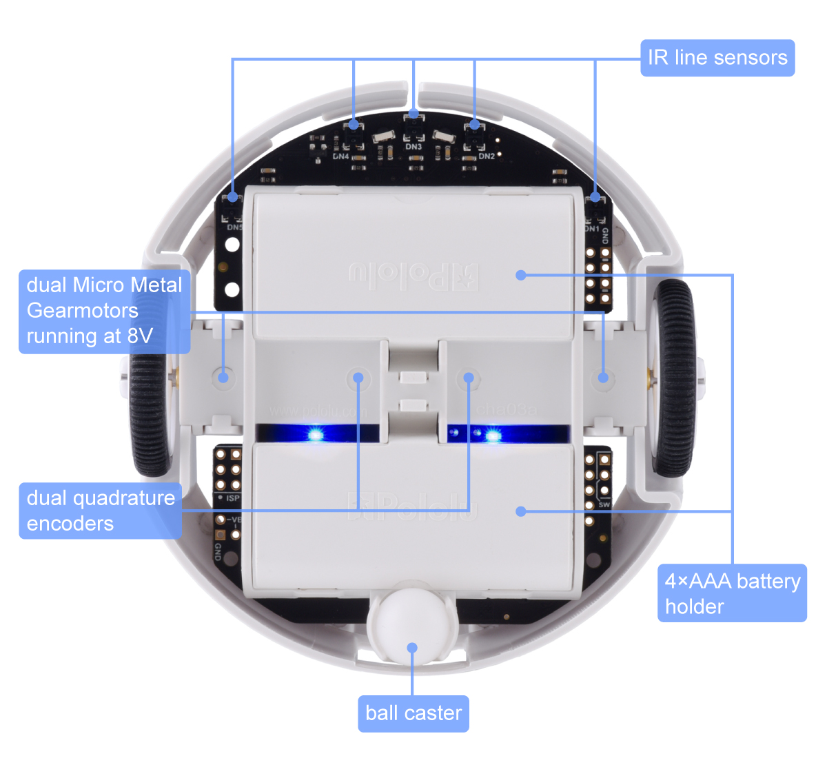
Figure 2. Under view of the 3pi+ robot.
Arduino IDE Setup
The first thing I noticed
when comparing 3pi and 3pi+ example code is the difference in libraries
being used. The 3pi utilizes the Pololu AVR C/C++ Library which doesn't
support the Pololu 3pi+ robot, so right away the previous 3pi maze
solving code is not able to simply be used on the 3pi+. After
discovering that the 3pi maze solving code was incompatible with the
3pi+ robot, Pololu's documentation explaining the code was analyzed.
The documentation used can be found here under the Example Project #2: Maze Solving section.
In addition to finding an explanation of the maze solving code, the
Arduino IDE also had to be setup in order to enable programming the
3pi+. The Pololu 3pi+ User's Guide
provides instructions on how to program the 3pi+. A driver for the 3pi+
can be installed in addition to adding Pololu to the boards manager and
installing the 3pi+ library. Below are some screenshots of the process,
after this initial setup the 3pi+ robot can then be programmed. You
also have the option of not installing Pololu A-Star Boards and instead
setting the board to Arduino Leonardo since they are similar enough to
allow this.
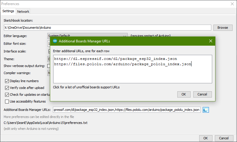
Figure 2. Screenshot of the Additional Boards Manager URLs window.
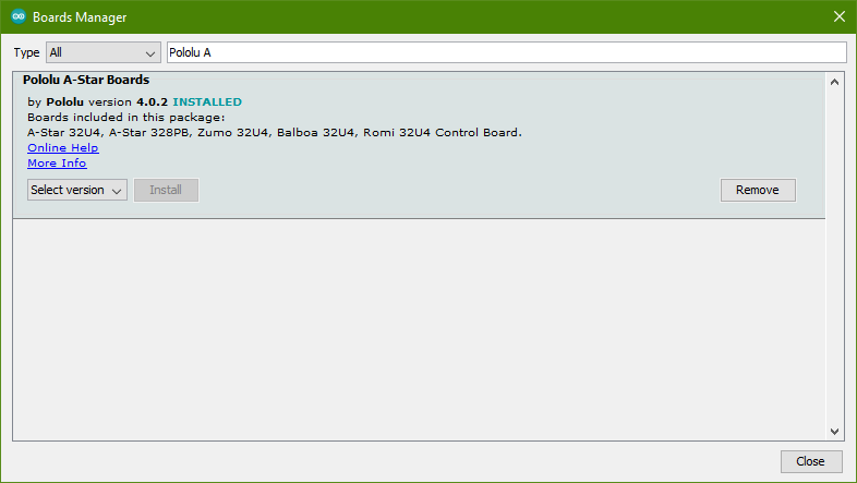
Figure 3. Screenshot of the Boards Manager window.
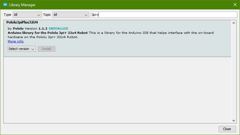
Figure 4. Screenshot of the Library Manager window.
Maze Solver Code
The original 3pi robot's maze solver example code can be found here.
Simply click where it says "Pololu Orangutan and 3pi Robot add-on for
the Arduino IDE". You can also download a copy of the example code by
clicking on the Pololu AVR C/C++ link shown above but that download is
for programming using Microchip Studio, not the Arduino IDE so it isn't
an .ino file. Extract the zip file and navigate to
...\libpololu-arduino-161018\libpololu-arduino\avr\libraries\Pololu3pi\examples\Simple3piMazeSolver
Where the Simple3piMazeSolver.ino file will be located. In addition to
examing the example code directly, the maze solving section in the Pololu 3pi Robot User's Guide was also examined in order to understand how it works.
Basic Functions Needed
Since the 3pi and 3pi+ robots
support using an LCD display and have built-in buttons, there is a menu
system that is controlled via the OrangutanLCD library and the
Pololu3piPlus32U4 library for the different robots respectively. Since
the libraries were different, I noted down what the functions were
doing in general terms.
There is a function to load custom characters, these characters are
used to display the current IR sensor readings on the LCD in the form
of a bar graph. A display readings function handles the actual
displaying of these readings. When the IR sensors are over a white
surface the bar graph is low. They increase in height depending on how
much they are above the black electrical tape.
The setup function that is needed in all Arduino sketches accomplishes
a few things to improve user experience. A welcome message and music
tune are played upon powering up. The name of the program is also
displayed ("Maze Solver") on the LCD. Afterwards the current battery
voltage is shown and the program waits for the user to press the switch
labelled B. After this an auto calibration loop runs. Auto calibration
is done by rotating the robot right and left and then utilizing a
calibrate function included in the library. This allows the IR sensors
to detect when there is a black line beneath them. After auto
calibration the current IR readings are displayed using the functions
discussed above until the user presses B once again. Another music tune
plays before the robot begins the maze solving process.
The main program loop handles moving the robot car. An while loop
executes the following functions until an end point is detected. There
is a follow
segment function that moves the robot forward until an intersection is
detected. This function doesn't simply tell the motors to move forward
at a set speed, it also compensates for any differences in the two
motor's power using a PID controller. The output of the PID controller
is then used to set the speed of the robot's motors. The follow segment
also checks the IR sensors so that the robot stops at an intersection.
An array of size 5 holds the IR line sensors readings for the sensors
seen above in the 3pi+ robot under view. A diagram of the array and the
sensors can be seen below.
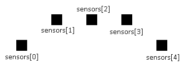
Figure 5. Sensor array diagram.
Using these sensors intersections can be detected base on the values
the IR line sensors return. Some more boolean variables keep track of
what directions are detected, these are found_left, found_right, and
found_straight. Below is an illustration of what the array holds
depending on the IR line sensor readings and what directions are found
e.g. when sensors[0] is greater than 100 then a left turn has been
found and so on.
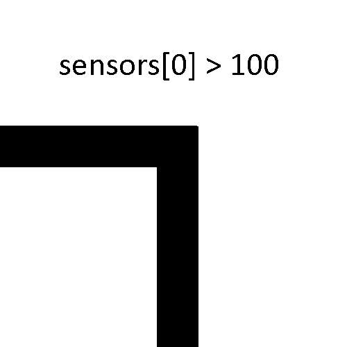
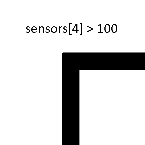
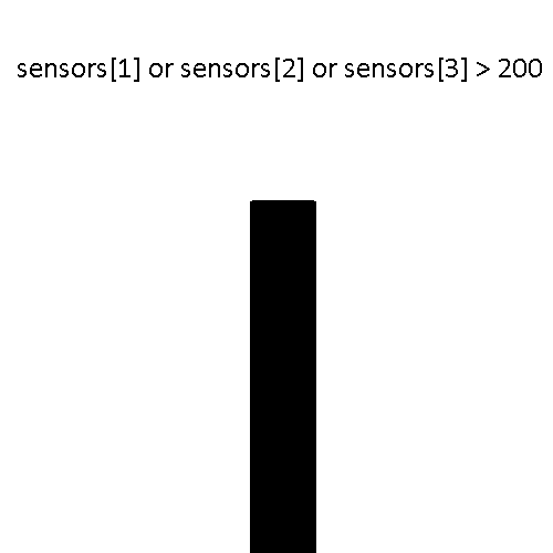
Figure 6. Illustrations of how the IR line sensors detect intersections.
Now that the program knows if there is a left turn, right turn, or
straight section found another function called select turn determines
what direction the robot should turn. The maze solver code follows a
"left-hand on the wall" approach to solving mazes. This means that the
robot will always prioritize left turns, if there is no left turn then
it goes straight, and if there is no right then the robot will continue
moving straight. If there is no left, right, or straight section
detected then it means that the robot has reached a dead end and the
direction the robot should turn will be backwards. A consequence of
using this strategy to solve mazes is that the maze cannot contain any
loops.
The select turn function returns a character specifying what turn the
robot should make. A variable called dir can hold 'L', 'S', 'R', or
'B'. This output is passed onto a function called turn. The turn
function sets the robot motors to the appropriate direction and power
in order to execute the turn.
While the robot is navigating the maze another array called path stores
the various turns the robot is making. A function called simplify path
detects when the robot returns to a previous intersection and modifies
the path to reduce the number of turns needed. An illustration of the
simplify path function is shown below. The red arrows indicate the
initial path the robot would choose while the blue arrows indicate the
simplified path.
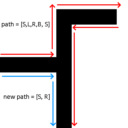
Figure 7. Illustration of how the simplify path function operates.
While the robot solves the maze, another function called display path
handles displaying the current stored path on the LCD. Since the
simplify path function runs before the display path function, the path
being displayed on the robot is updated in real time.
Within the while loop that is executing the follow segment function,
the turning functions, and the path functions, there is a check when
reading the IR line sensors that checks if an end point is detected.
When designing a maze, the end point should be constructed with a large
black box as shown below. When this condition is satisfied the while
loop is broken and the LCD displays that the maze has been solved.
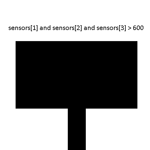
Figure 8. Illustration of a maze end point and the condition associated with it.
Now that the maze has been solved, the robot enters another while loop.
This while loop waits for the user to press the B button before it
executes turns based on the simplified path. Now the robot is able to
resolve the maze more efficiently. The original functionality of the
3pi maze solver code was replicated using the updated 3pi+ libraries. A
demonstration video of the 3pi+ maze solver is shown below.
I also included an option to select the 3pi+ version. Pololu has three
versions of the 3pi+ robot, these being Standard, Hyper, and Turtle.
The differences between these versions are basically how fast they are
able to move. When selecting the version an appropriate max speed and
calibration speed value are set.
Maze Solver PCB Design
In addition to understanding
the Pololu 3pi+, work has been started on creating a more general maze
solving robot kit. A PCB will be designed to simplify the building
process to create a product that is readily usable.
The first steps to creating a maze solver PCB design was to ensure the
necessary hardware is able to function together. The ATmega328PU was
the chosen microcontroller due to the ease of use in prototyping the
maze solver PCB. The analog inputs were dedicated to the five infrared
sensors (the TCRT5000). The motors being used are 6V micro metal
gearmotors with Pololu wheels and a Pololu ball caster for balancing.
The video below shows the barebones ATmega328PU and LCD testing in
addition to verifying that the L293D motor driver is able to control
the 6V micro metal gearmotors. The final test is verifying that the
prototype maze solver is able to read IR sensor values in addition to
the previous tests.
The schematic below shows the power input and switch, the bare bones ATmega328PU, and the pin headers for the LCD.
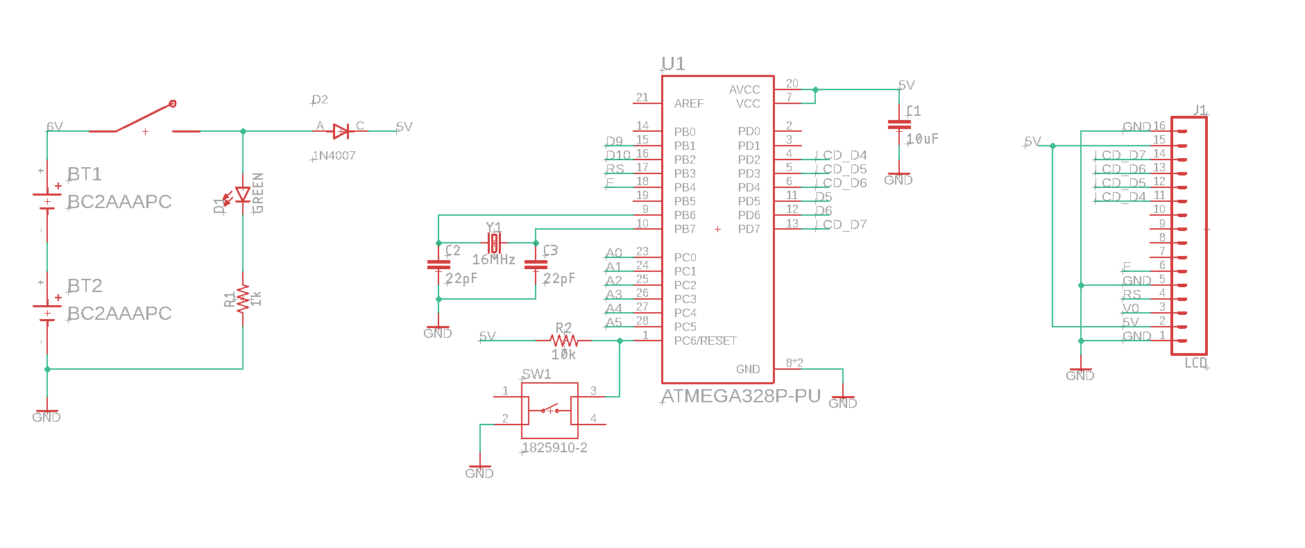
Figure 9. Schematic of the power input, ATmega328PU microcontroller, and header pins for the LCD.
The second schematic below shows the infrared sensor wiring. The emitters are constantly on.
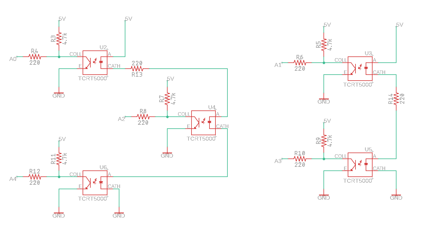
Figure 10. Schematic of infrared sensor wiring.
The final part of the schematic is shown below. The L293D motor driver
and the pin headers for the micro metal gearmotors. The motors are able
to be soldered to a PCB directly using the spacing of a 4 pin
connector, so I just used that for ease of use later in the final PCB.
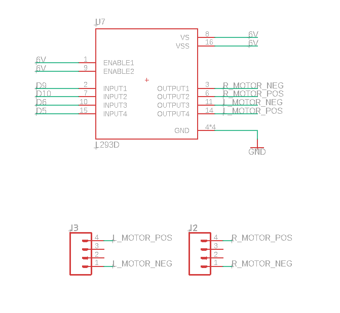
Figure 11. Wiring schematic for the L293D motor driver.
Using these schematic the prototype maze solver robot was created on
protoboard. This is made up of 2 protoboards secured using plastic
screws for now. A top view of the maze solver robot wiring is shown
below in the figures below. The upper side shows the ATmega328PU
microcontroller, the L293D motor driver, and the micro metal
gearmotors. The bottom side displays more wiring underneath in addition
to the IR sensors and Pololu ball caster part (the white ball).
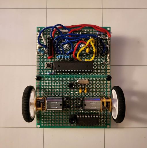
Figure 12. Top view of the maze solver robot.
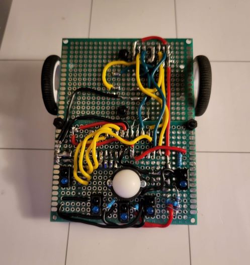
Figure 13. Bottom view of the maze solver robot.
Wiring for the LCD was done using an additional smaller protoboard that
also contains the power wiring. A power switch can be seen above the
LCD along with a diode, LED, and potentiometer for controlled LCD
contrast. This smaller protoboard is connected to the AA battery pack
used to power the maze solver robot.
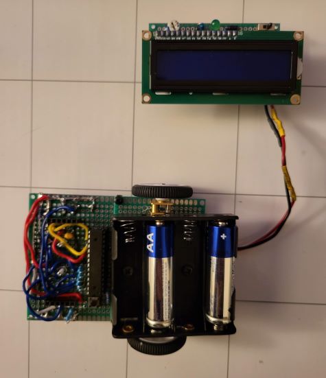
Figure 14. View of the LCD and battery protoboard adapter.
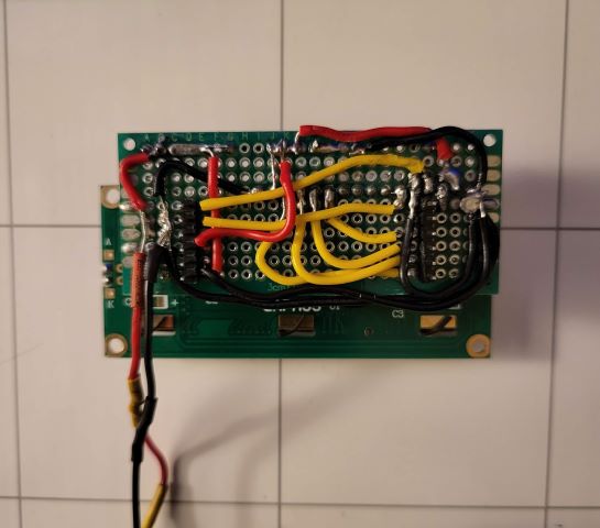
Figure 15. Back view of the LCD and battery protoboard adapter.
A look at the maze solver powered on can be seen below from two different angles.
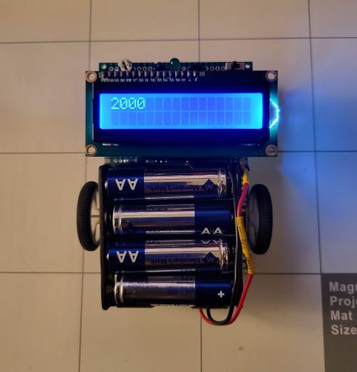
Figure 16. Top view of the maze solver robot powered on.
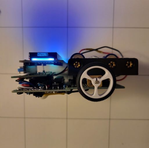
Figure 17. Side view of the maze solver robot powered on.
Functionality from the Pololu 3pi+ robot libraries was attempted to be
ported over to function on the ATmega328PU but has not yet been
completed. The method of reading the IR line sensors using the Pololu
libraries has additional processing to create a range of numbers from 0
to 4000 indicating where the line is sensed. This is why the LCD
displays 2000 in figure 16 above. In addition to this, controlling the
motors using the L293D motor drivers differs from the 3pi+. The same
code used to move the robot runs a lot faster compared to the 3pi+
robot as shown in the second demonstration video. A calibration test
was ran and the robot fails to rotate all the way around despite
doubling the amount of time the motors are activated in a for loop.
The current DIY maze solver sketch can be found here.
The current Pololu 3pi+ maze solver code can be found here.
The current Pololu 3pi maze solver code can be found here.