Task 1: Repeat the simulation in Section 1 - 3.
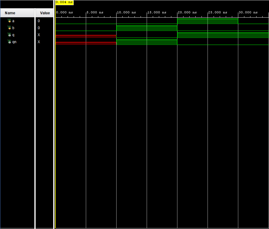
Figure 1: SR Latch simulation.
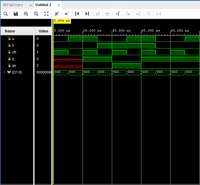
Figure 1.1: SR Flip Flop simulation.
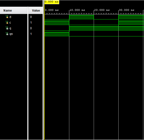
Fiugre 1.2: Level Triggered D Flip-Flop simulation.
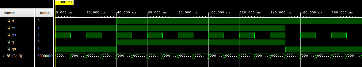
Fiugre 1.3 Edge Triggered D Flip-Flop Simulation.
Task
2: Write the testbenches and run simulations for Sections 4 and 5.
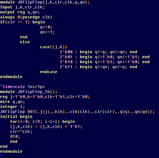
Figure 2: Edge Triggered JK Flip-Flop test bench.
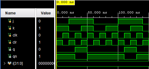
Figure 2.1: Edge Triggered JK Flip-Flop simulation.
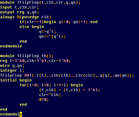
Figure 2.2: T Flip-Flop Code test bench.
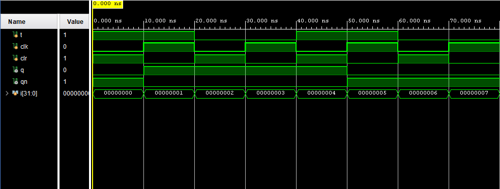
Figure 2.3: T Flip-Flop simulation.
Task 3: Repeat all the work in Section 8 and complete the task described in the end of Section 8.
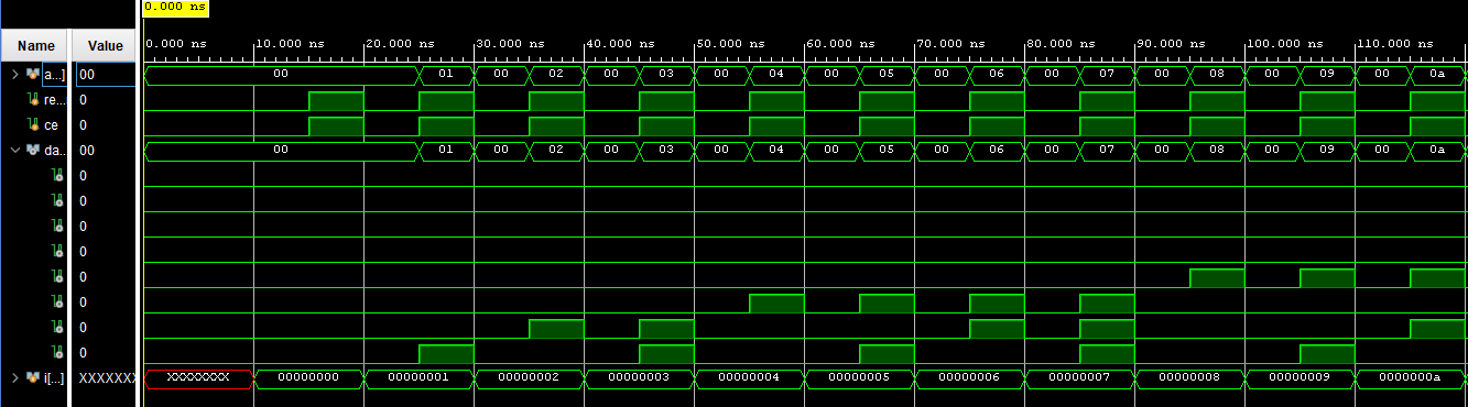
Figure 3: ROM 8-bit binary number simulation.
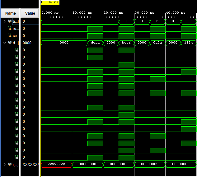
Figure 3.1: ROM hex number simulation.
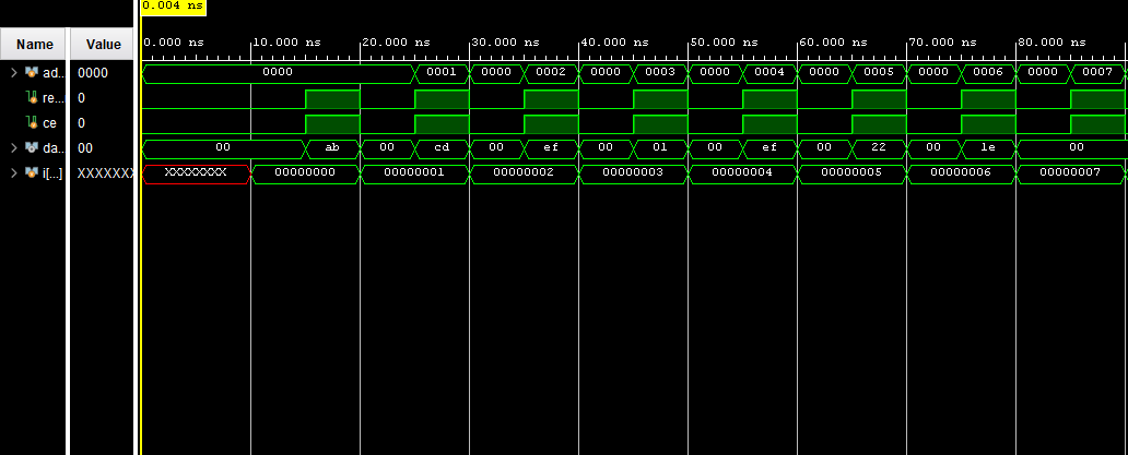
Figure 3.2: ROM 8-bit Hex simulation.
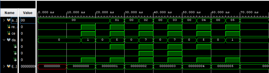
Figure 3.3: ROM 3-bit binary number simulation.
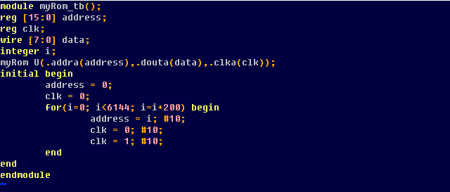
Figure 3.4: IP core myRom test bench .
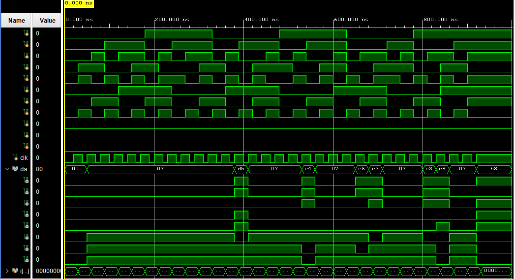
Figure 3.5: myRom simulation.
Figure 2: Edge Triggered JK Flip-Flop test bench.
Figure 2.1: Edge Triggered JK Flip-Flop simulation.
Figure 2.2: T Flip-Flop Code test bench.
Figure 2.3: T Flip-Flop simulation.
Task 3: Repeat all the work in Section 8 and complete the task described in the end of Section 8.
Figure 3: ROM 8-bit binary number simulation.
Figure 3.1: ROM hex number simulation.
Figure 3.2: ROM 8-bit Hex simulation.
Figure 3.3: ROM 3-bit binary number simulation.
Figure 3.4: IP core myRom test bench .
Figure 3.5: myRom simulation.