CE 433 Spring 2024 Midterm Sahra Genc sggenc@fortlewis.edu
Midterm
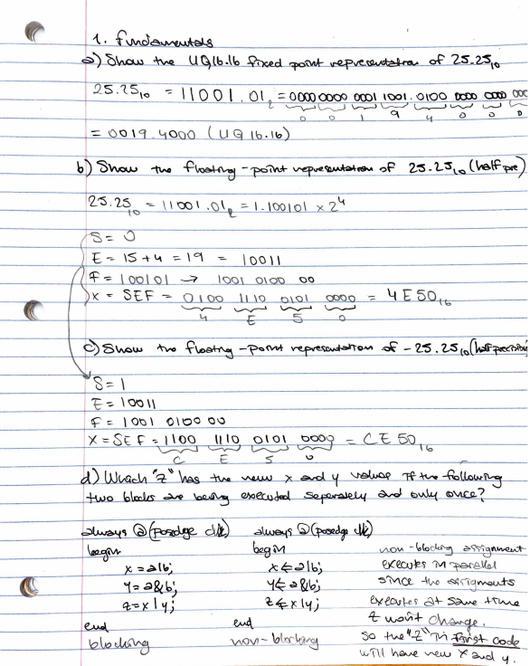
1. Fundamentals
(a) Show the UQ16.16 fixed point representation of 25.25 (10). (5 points)
(b) Show the floating-point representation of 25.25 (10) (half precision). (5 points)
(c) Show the floating-point representation of -25.25 (10) (half precision). (5 points)
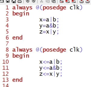
(d) Which ‘z’ has the new x and y values if the following two blocks are being executed
separately and only once? (5 points)
Figure 1. Answers to 1a,1b,1c and 1d
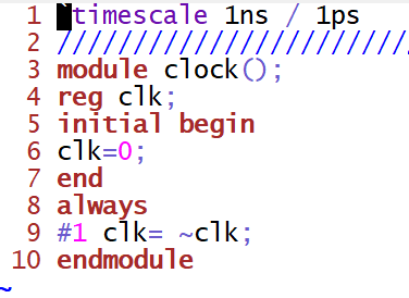
2. Make a 2 ns period clock waveform. Show the code and the simulation results for credits. (10
points)
Figure 2. The code for 2ns period clock waveform
Figure 3. The simulation results for 2ns period clock waveform
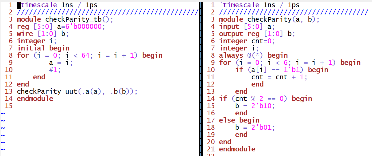
3. Design a module which has a 6-bit input bus. The module checks if there are even number of
one’s or odd number of one’s in the input. The two output bits shows output =2’b10 when it’s
even, shows output = 2’b01 when it’s odd. Show simulation results that displays both outputs.
(10 points)
Figure 4. The code for question 3
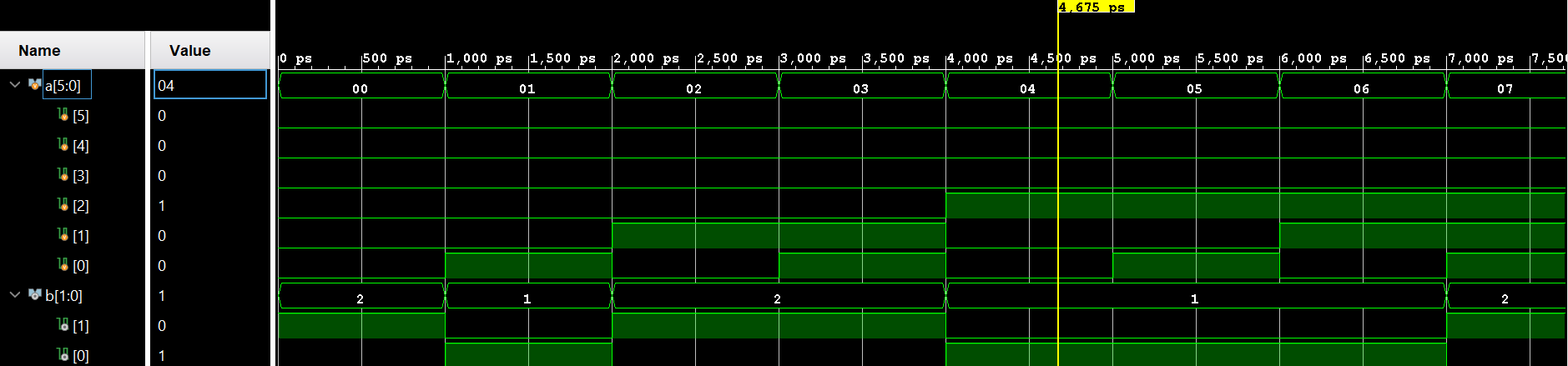
Figure 5. The simulation for question 3
4. (a) Given that the following state diagram is a sequence detector. What the sequence of 4-bit
binary code it detects? (10 points)
(b) Design a sequence detector to detect a serial input of 1010 by completing the following tasks:
(50 points, demonstration video required)
• Draw the state diagram similar to what is shown in (a). (10 points)
• Find the truth table of the sequential circuit. (10 points)
• Find the logic expressions of the sequential circuit. (10 points)
• Code it up using the behavioral Verilog model. (10 points)
• Implement it on the Basys 3 board. The serial input must be taken by a switch, the values
of the switch are registered by another switch (as a clock). When the sequence is correct,
the monitor shows a solid green color (through VGA). When the sequence is wrong, it
returns to a solid red color. Continuous inputs are allowed which means the customer is
allowed to keep registering code into it and whenever 4’b1010 is detected, it turns green
otherwise, it turns red. (10 points)
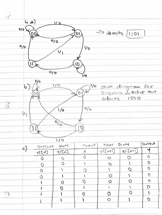
Figure 6. Answer to 4a and the state diagram and the truth table to 1010 sequence detector
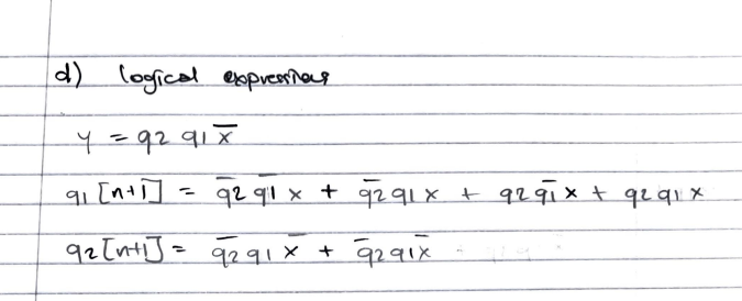
Figure 7. Logical expression to 1010 detector
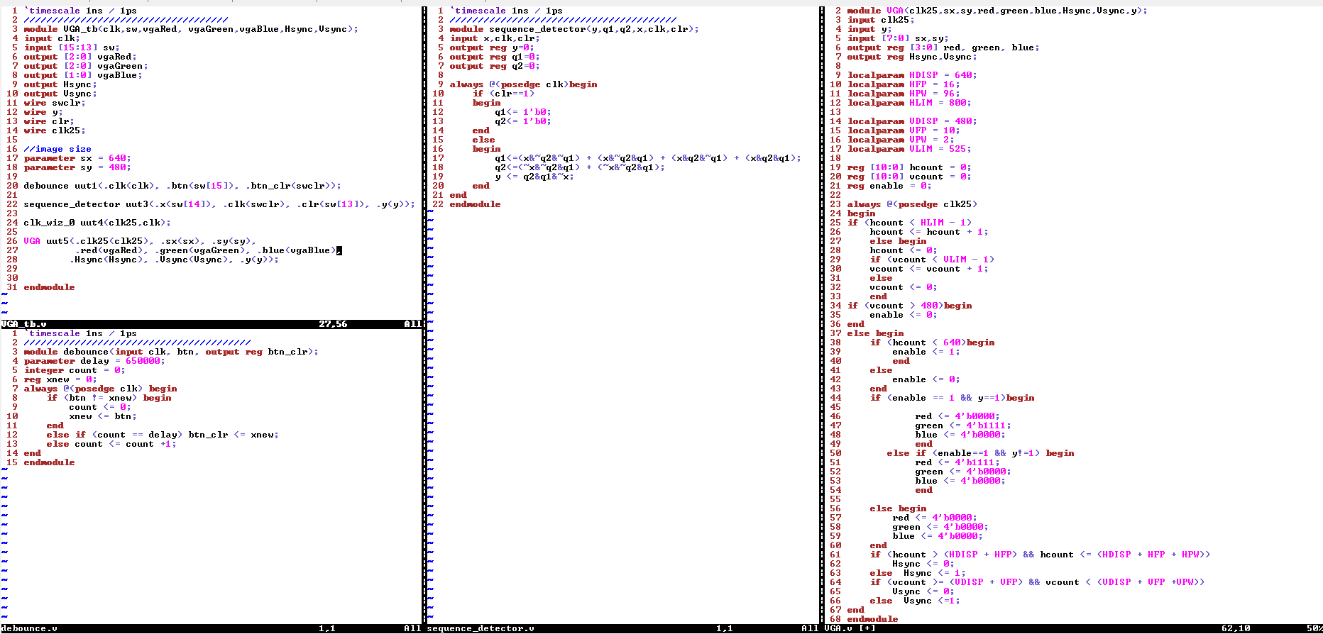
Figure 8. The code for detecting 1010 sequence and displaying green on the monitor and red otherwise