Introduction
This lab focuses on the design and implementation of a 3-bit adder/subtractor in 2's complement notation using Verilog and Vivado. The lab is divided into three tasks: Task 1 involves creating the adder/subtractor circuit with the results displayed through LEDs; Task 2 expands upon this by incorporating a seven-segment display alongside LEDs for output visualization. Finally, Task 3 introduces the utilization of Serial In Parallel Out (SIPO) to input two 3-bit numbers into registers, with computation triggered by a single switch.
Week 1:
Task 1: Use switches as the 3-bit inputs, use 'leds' to show the binary results.
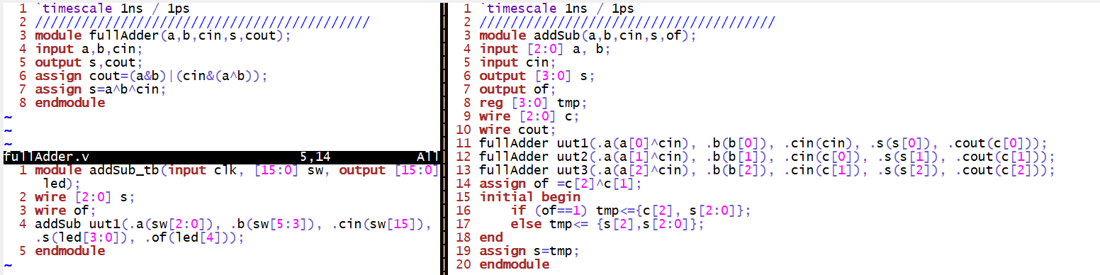
Figure 1. The implementation of the 3-bit Adder/Subtractor with using leds
Video 1. The demonstration of the 3-bit Adder/Subtractor with using leds
Task 2: Use switches as the 3-bit inputs, use seven-segment displays to show the decimal result, make sure have the 'minus' sign in front of the decimal number if the result is negative.
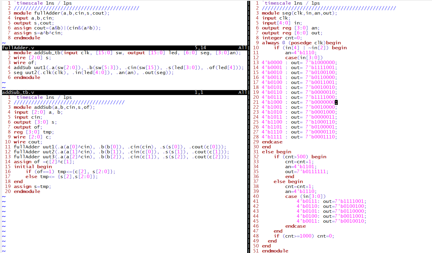
Figure 2. The implementation of the 3-bit Adder/Subtractor with displaying on the ssd
Video 2. The demonstration of the 3-bit Adder/Subtractor with displaying on the ssd
Week 2:
Task 3: Use Serial In Parallel Out (SIPO) to input two 3-bit numbers [2:0] A, and [2:0] B, into the registers, then use one switch to trigger the computation.
This implementation uses the modules shown in Figure 2. and it also includes the sipo and debounce module we used in the quiz.
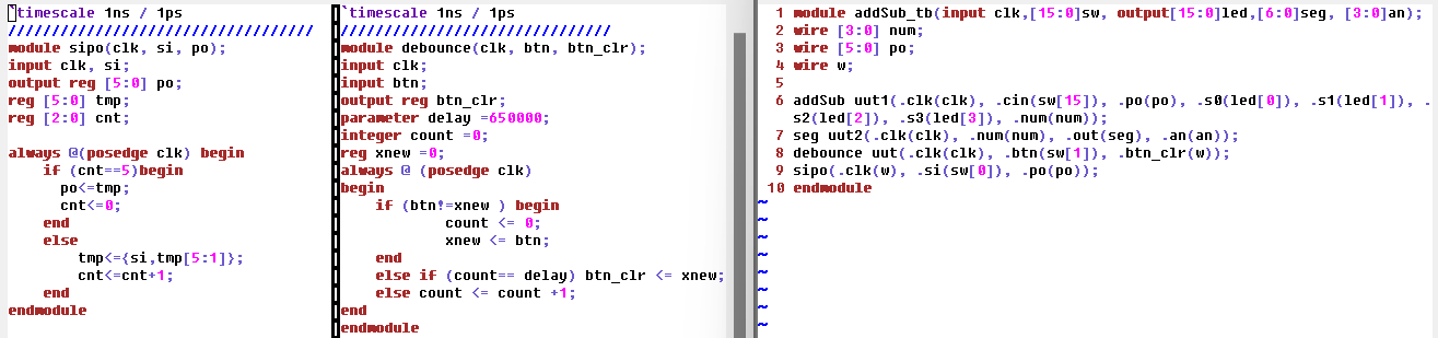
Figure 3. The implementation of the 3-bit Adder/Subtractor with using SIPO
Video 3. The demonstration of the 3-bit Adder/Subtractor with using SIPO
This lab focuses on the design and implementation of a 3-bit adder/subtractor in 2's complement notation using Verilog and Vivado. The lab is divided into three tasks: Task 1 involves creating the adder/subtractor circuit with the results displayed through LEDs; Task 2 expands upon this by incorporating a seven-segment display alongside LEDs for output visualization. Finally, Task 3 introduces the utilization of Serial In Parallel Out (SIPO) to input two 3-bit numbers into registers, with computation triggered by a single switch.
Week 1:
Task 1: Use switches as the 3-bit inputs, use 'leds' to show the binary results.
Figure 1. The implementation of the 3-bit Adder/Subtractor with using leds
Video 1. The demonstration of the 3-bit Adder/Subtractor with using leds
Task 2: Use switches as the 3-bit inputs, use seven-segment displays to show the decimal result, make sure have the 'minus' sign in front of the decimal number if the result is negative.
Figure 2. The implementation of the 3-bit Adder/Subtractor with displaying on the ssd
Video 2. The demonstration of the 3-bit Adder/Subtractor with displaying on the ssd
Week 2:
Task 3: Use Serial In Parallel Out (SIPO) to input two 3-bit numbers [2:0] A, and [2:0] B, into the registers, then use one switch to trigger the computation.
This implementation uses the modules shown in Figure 2. and it also includes the sipo and debounce module we used in the quiz.
Figure 3. The implementation of the 3-bit Adder/Subtractor with using SIPO
Video 3. The demonstration of the 3-bit Adder/Subtractor with using SIPO