CE 433 Spring 2024 Lab 4: Combinational Logic Blocks Sahra Genc sggenc@fortlewis.edu
LAB 4:Combinational Logic Blocks
Introduction: In this lab, we were assigned to create a
traffic light system using the Basys 3 board. The purpose was to
understand the logic behind the two way traffic lights and to create a
plan for their different states, and to use Verilog to make them
function. We also tested our work in Vivado and use LEDs on the board
to visualize the traffic light changes. Alternatively, we're making our
system adaptable to busy times by letting one side stay green for
longer during rush hours.
Task 1: Think about how many states
the two-way traffic lights may have for each cycle. The green light on
one side truns yellow and then turns red before the other light changes
to green from red. Draw the truth table for all the states in one cycle
of the traffic light change. Simplify the logic equations for each
light using the K map. Design the Verilog model and the testbench, show
the simulation results in Vivado. Use 6 leds on your Basys 3 board to
implement the design. Show the demo video for credits.
Figure 1. Kmap and logic equations for the traffic lights
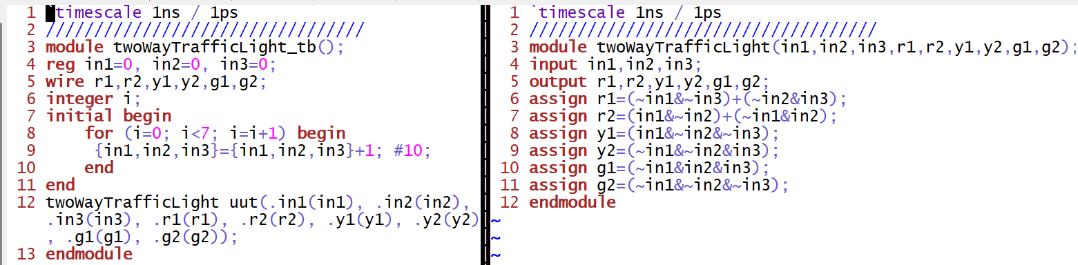
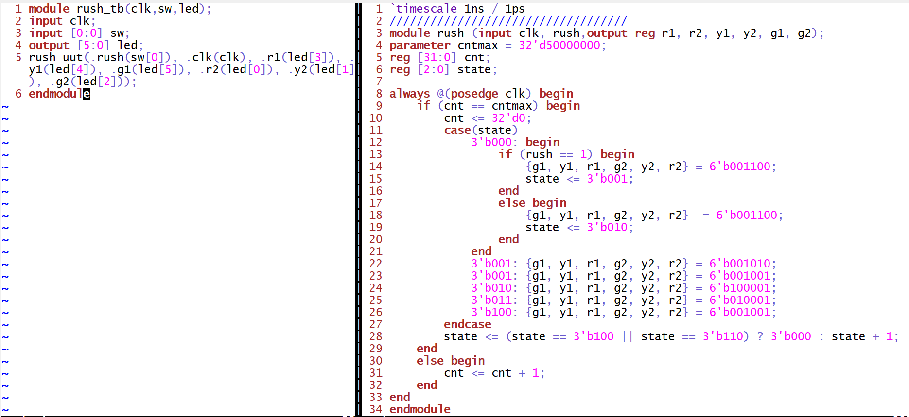
Figure 2. Code implementation for the simulation of the two way traffic lights 
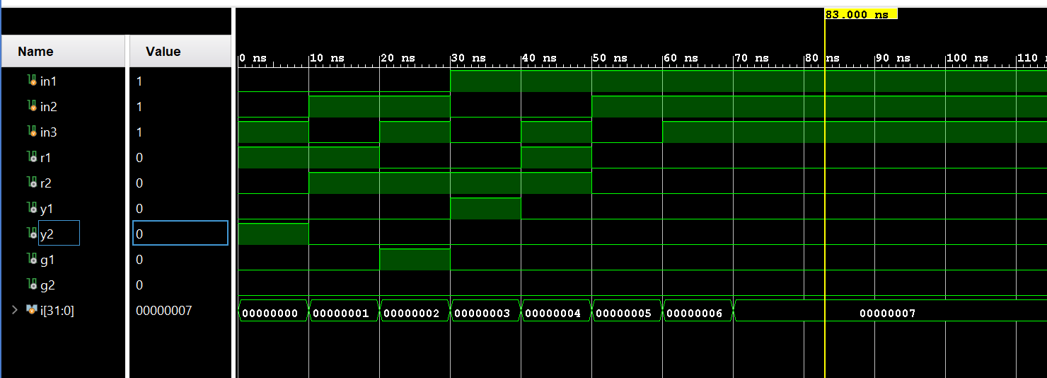
Figure 3. Vivado simulation of the two way traffic lights
The code shown in Figure 4. implements a two-way traffic light system with sequential state changes.
The trafficLights module operates with a state machine, cycling through
different states to control two sets of traffic lights. The "cnt"
counter is used to control the state transitions, and the LED output
signals represent the current state of the traffic lights. The
twoWayTrafficLight_tb_FPGA is the testbench that connects the clock
signal and LED outputs for the FPGA.
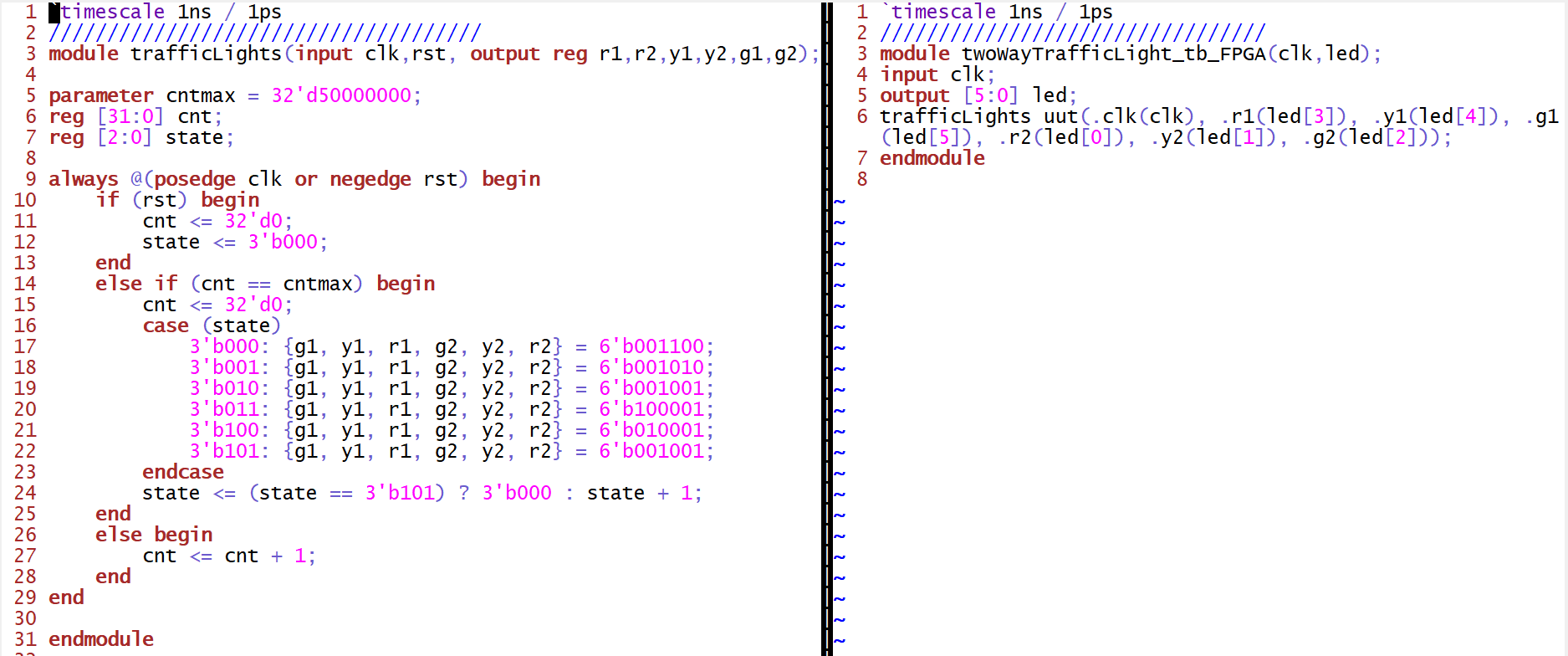
Figure 4. Code implementation for the FPGA of the two way traffic lights
Video 1. Demonstration of the two way traffic lights on the FPGA
Task 2: While
the first problem cycles through all states with the same durations,
during rush hours, the busy road has a longer duration for the green
light than the red light. Use a switch to trigger the rush hour mode,
which keeps one of the green lights ON for double the duration compared
to the other road. Show the code, code explanation, and demo video in
your report.
The code shown in Figure 5. is similar to the code shown in Figure 4.,
it utilizes a state machine with a counter "cnt" to control state
transitions based on a clock signal. The traffic light states are
determined by the "rush" input, allowing for a rush mode where the
traffic lights respond differently.
Figure 5. Code implementation for the FPGA of the two way traffic lights in rush hour mode
Video 2. Demonstration of the two way traffic lights in rush hour mode on the FPGA
Discussion: Overall, in this lab we figured out how traffic lights
cycle through different states, implement it on Verilog, and tested it
out in Vivado. Moreover, the integration of the rush hour mode,
triggered by a switch, showed the adaptability of our system to dynamic
traffic scenarios.