CE 433 Spring 2024
Homework 6: Video Graphics Array (VGA)
Sahra Genc
sggenc@fortlewis.edu
HOMEWORK 6:Video Graphics Array (VGA)
Task 1: Repeat the work in Section 2. Show the code, explanation, and a demo video.
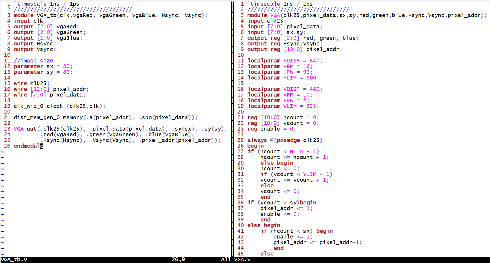
The VGA module shown in Figure 1.
creates VGA signals, incorporates Hsync, Vsync, and color signals for
pixel presenation. It uses the parameters HDISP, VDISP, HFP, VFP, HPW,
and VPW to define display timing and resolution. Counters (hcount and
vcount) track pixel positions within the display area, updating with a
25 MHz clock. Synchronization signals are generated based on these
counts. Pixel data is retrieved from memory using pixelAddr, and the
module extracts red, green, and blue components for output. When the
pixel position goes over the specified resolution , the pixel address
resets, and data process is disabled.
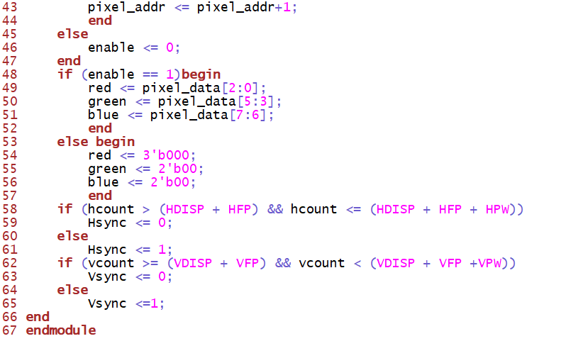
Figure 1. The implemenation of displaying image with VGA
Video 1. The demonstration of displaying image with VGA
Task 2: Replace the clock
generator IP with a self-made clock divider module that generates 25MHz
clock. Demonstrate that it works for the rest of the circuit.Show the
code, explanation, and a demo video.
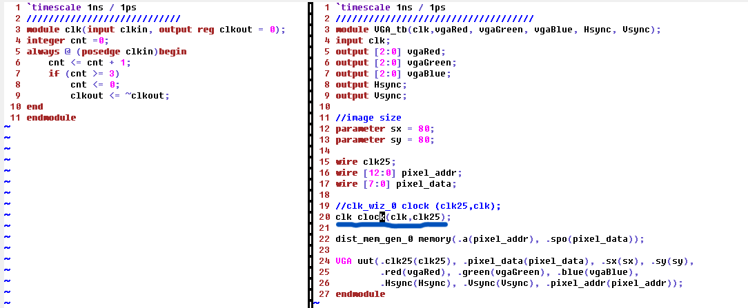
In this part the same VGA module used but a self-made clock divider
module used intead of the clock generator. Clk module syncs the VGA
operation using a divided clock from the input clock. The counter (cnt)
divides the input clock frequency by 4, resulting in a 25 MHz output
clock. The output toggles based on cnt, providing a slower clock signal.
Figure 2. The implemenation of self-made clock divider for displaying image with VGA
Video 2. The demonstration of displaying image with VGA with self-made clock divider
Task 3: Complete the two examples in Section 3. Show the code, explanation, and a demo video.
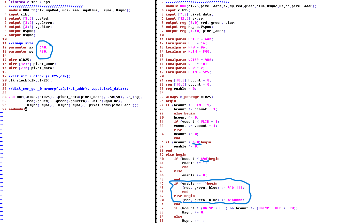
The code shown in Figure 3. uses the same VGA module but initilizes the
all the colors values to high and it results in white color display on
the monitor. Also on the testbench the sx and sy values are maximized
so that white color displays on the whole screen.
Figure 3. The implemenation of displaying full white screen on the monitor with VGA
Video 3. The demonstration of displaying full white screen on the monitor with VGA
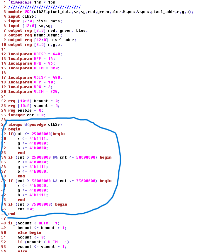
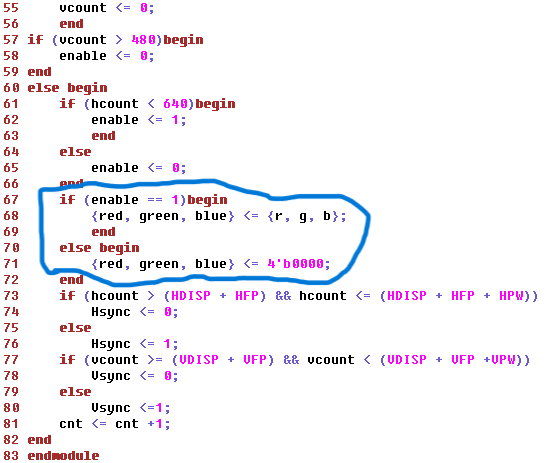
The module shown in Figure 4.
module incorporates a counter (cnt) to alternate between different
color patterns at specific intervals and it results in flashing red,
green and blue color on the monitor.
Figure 4. The implemenation of flashing RGB on the monitor with VGA
Video 4. The demonstration of flashing RGB on the monitor with VGA