CE 433 Spring 2024
Homework 5: Sequential Circuit
Sahra Genc
sggenc@fortlewis.edu
HOMEWORK 5: Sequential Circuit
Task 1:
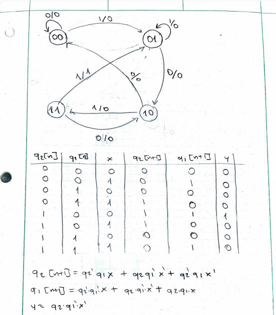
In Section 1, don't look at the logic equations provided to you. From
the state table, find the logic equations for q1(n+1) and y and draw
the sequential circuit for q1(n+1) and y.
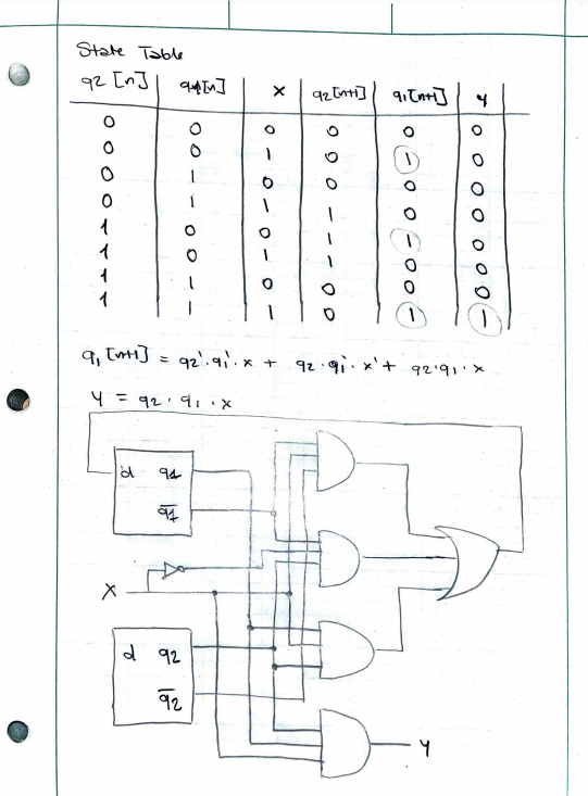 Figure 1. Logic Equations and Sequential Circuit for q1[n+1] and y
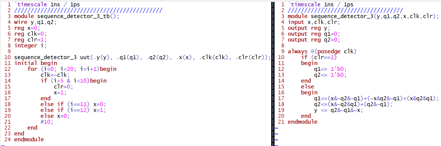
Task 2: Repeat the work in Section 3. Use two methods, the given one and the behavioral one. Show simulation results.
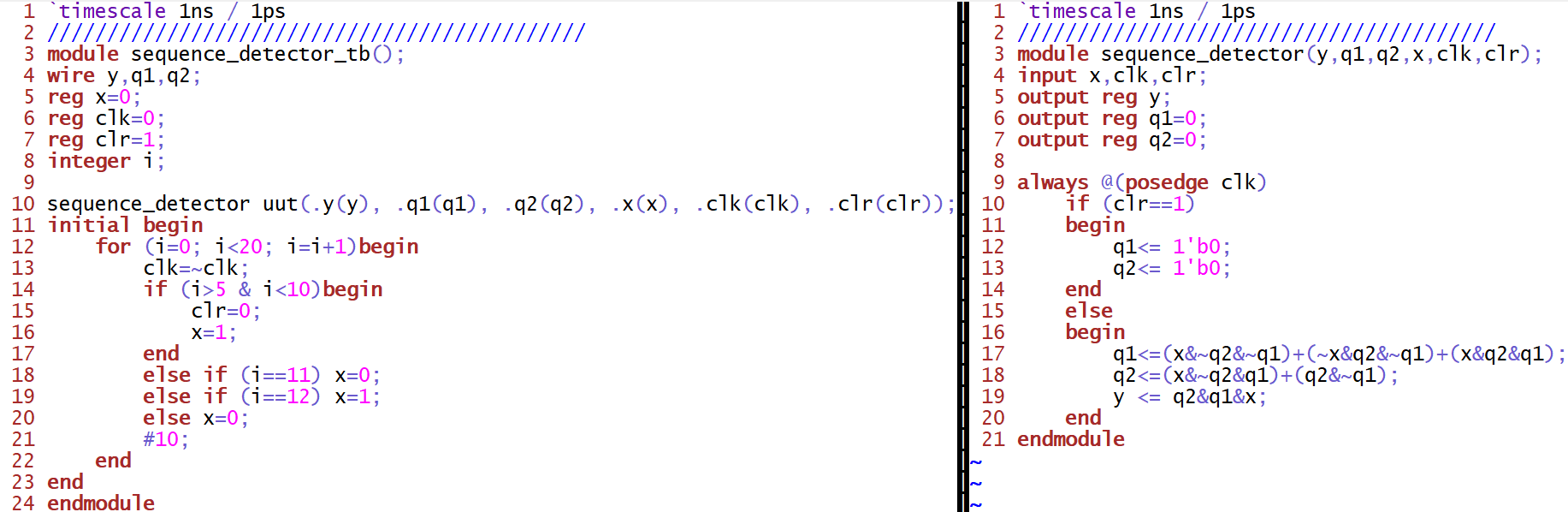 Figure 2. Gvim windows snapshot of the Sequence Detector implemenation
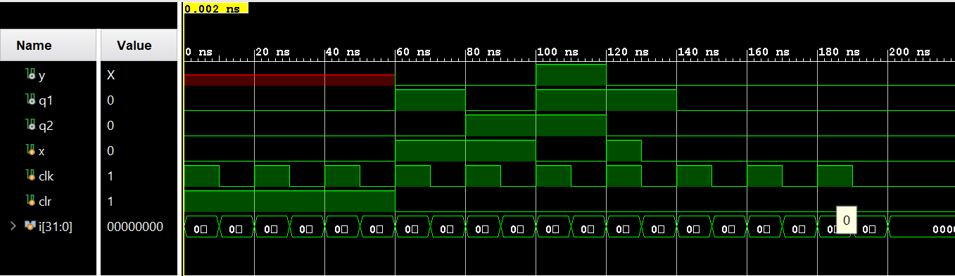
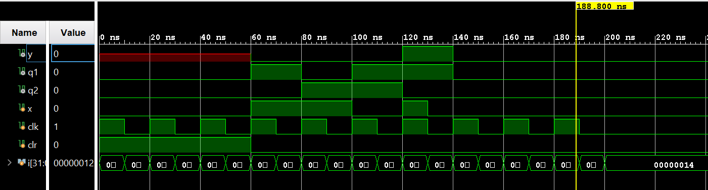 Figure 3. Vivado simulation of the Sequence Detector
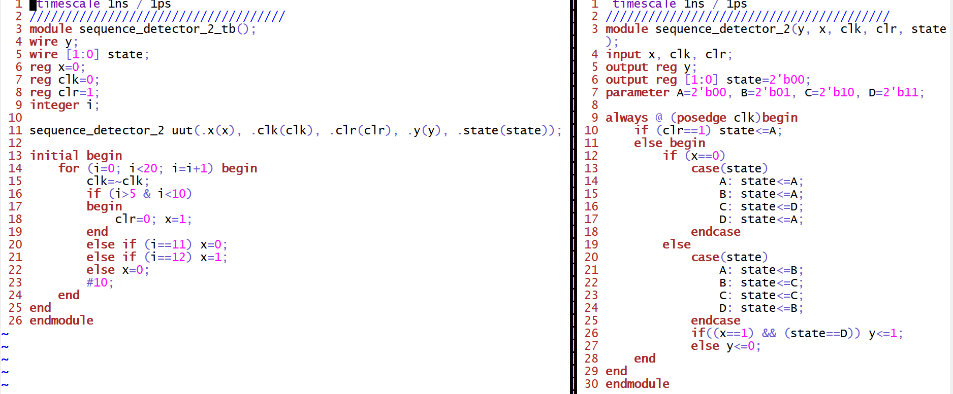 Figure 4. Gvim windows snapshot of the Sequence Detector with behavioral modeling implemenation
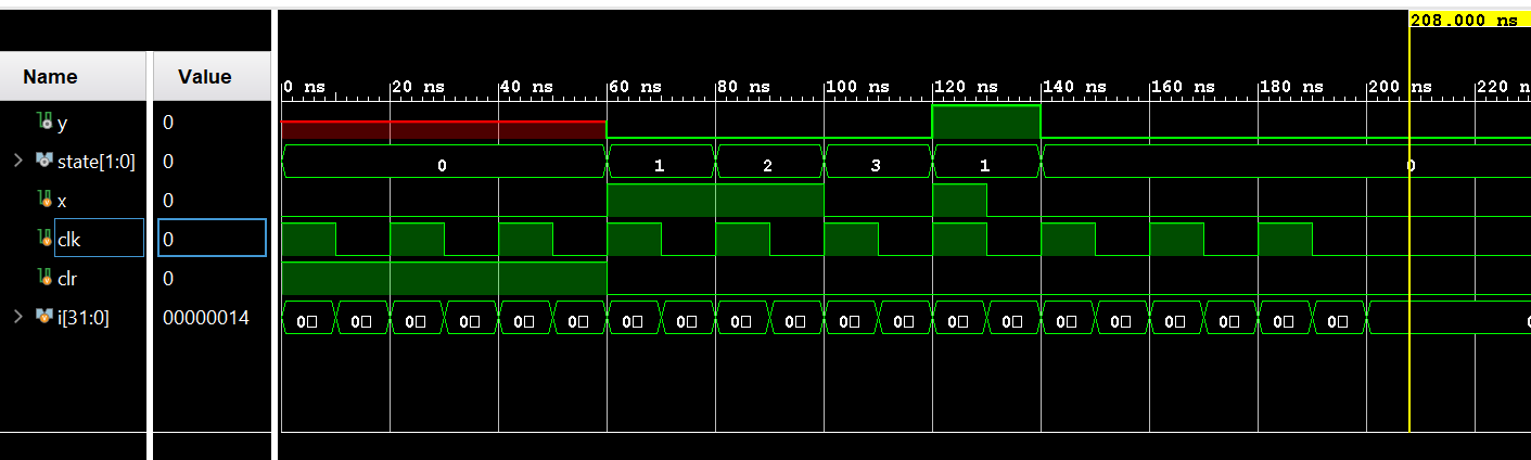 Figure 5. Vivado simulation of the Sequence Detector with behavioral modeling
Task 3:
Similar to the sequence detector in Section 3, change the sequence to
be detected to 1011, design the state diagram, draw the truth table,
find the logic equations, and design the verilog module and testbench
to verify the logic.
Task 4: Simulate the four types of shift registers in Section 5.
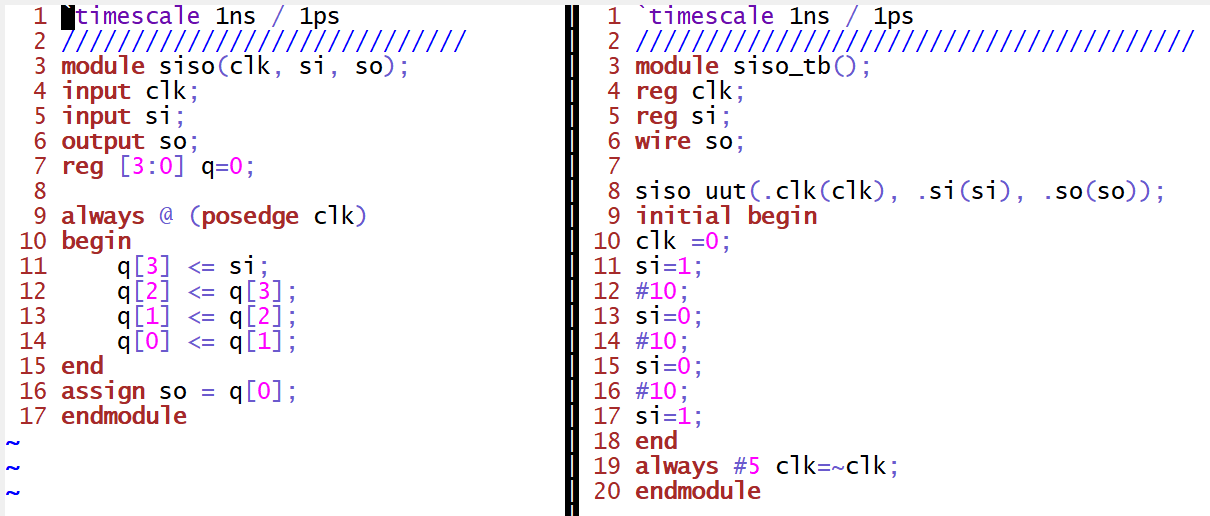 Figure 9. Gvim windows snapshot of the Serial-In Serial-Out shift register implemenation
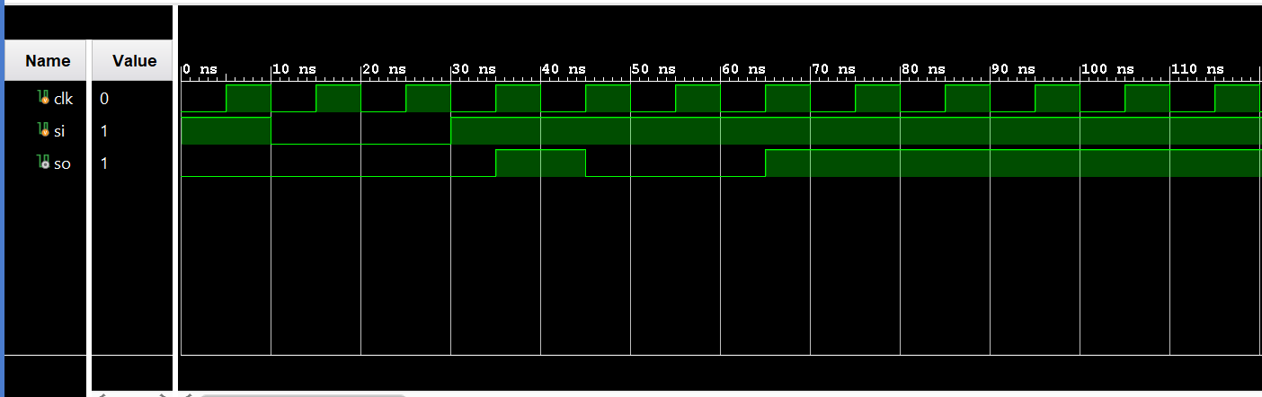 Figure 10. Vivado simulation of the Serial-In Serial-Out shift register
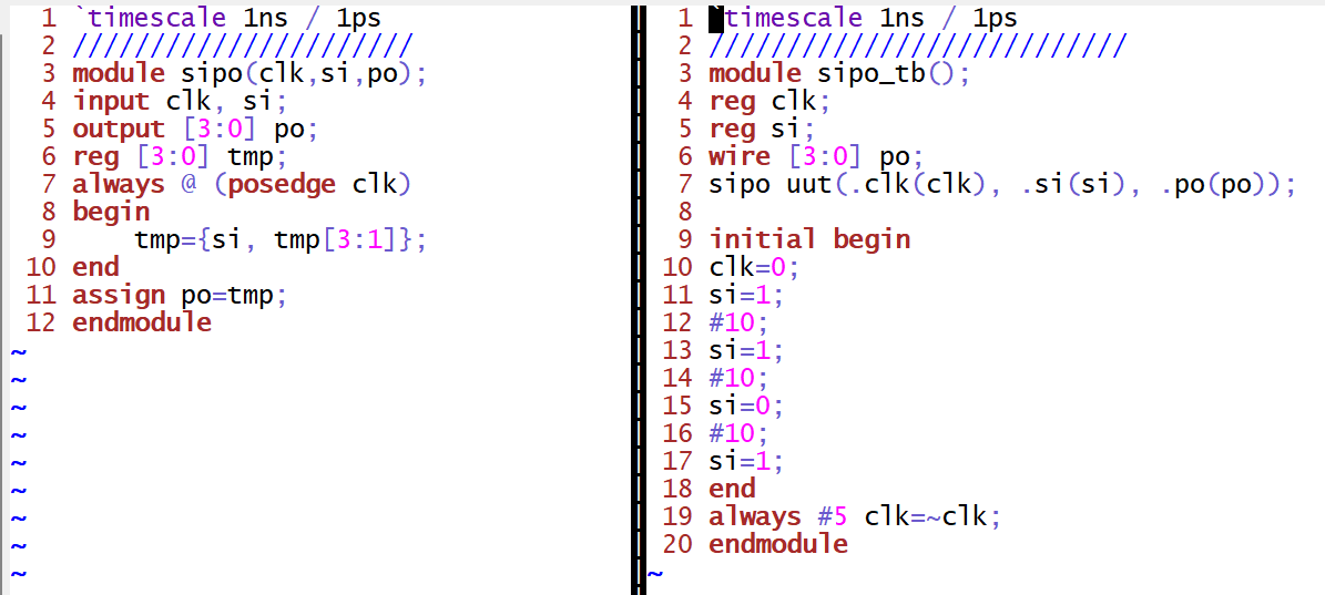 Figure 11. Gvim windows snapshot of the Serial-In Parallel-Out shift register implemenation
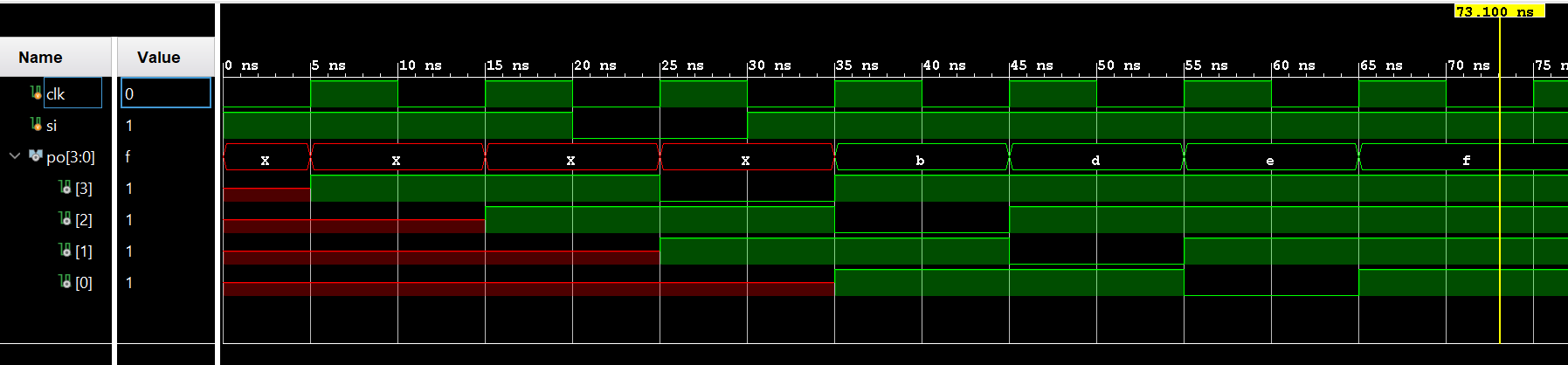 Figure 12. Vivado simulation of the Serial-In Parallel-Out shift register
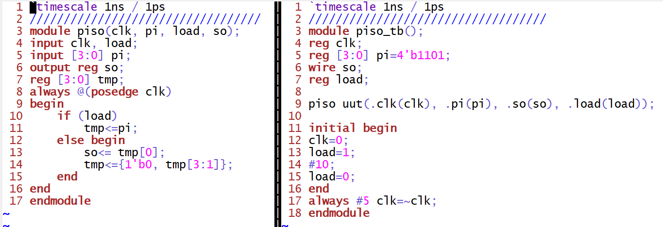 Figure 13. Gvim windows snapshot of the Parallel-In Serial-Out shift register implemenation
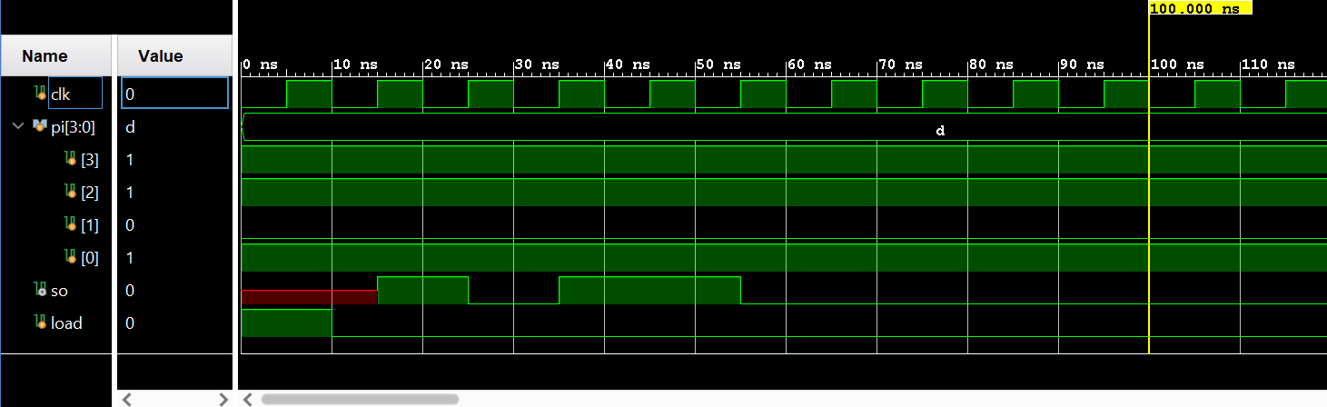 Figure 14. Vivado simulation of the Parallel-In Serial-Out shift register
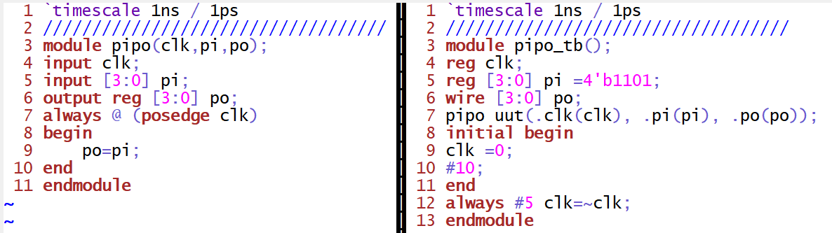 Figure 15. Gvim windows snapshot of the Parallel-In Parallel-Out shift register implemenation
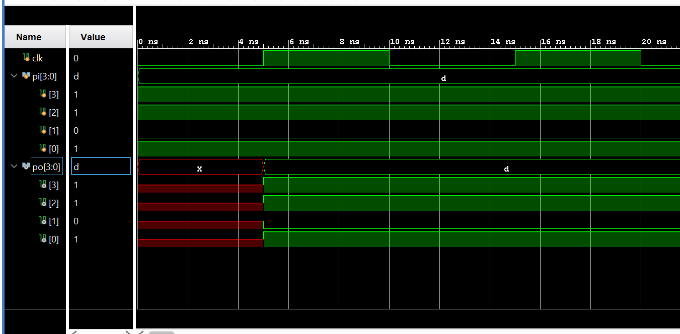 Figure 16. Vivado simulation of the Parallel-In Parallel-Out shift register
Task 5: Build a counter module and show the simulation results.
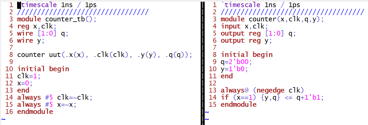 Figure 17. Gvim windows snapshot of the 2 bit counter implemenation
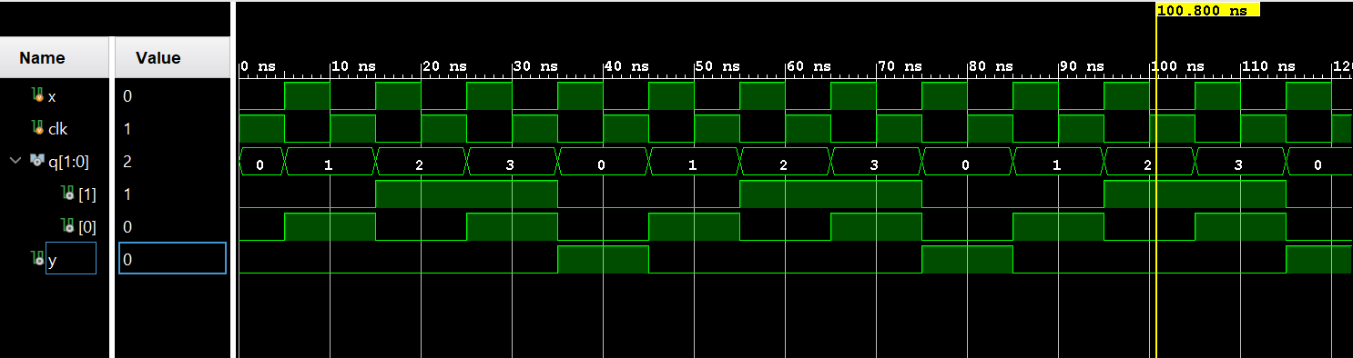 Figure 18. Vivado simulation of the 2 bit Counter
Task 6: Find the logic equation of the following circuit and implement it in verilog. Show the simulation results.
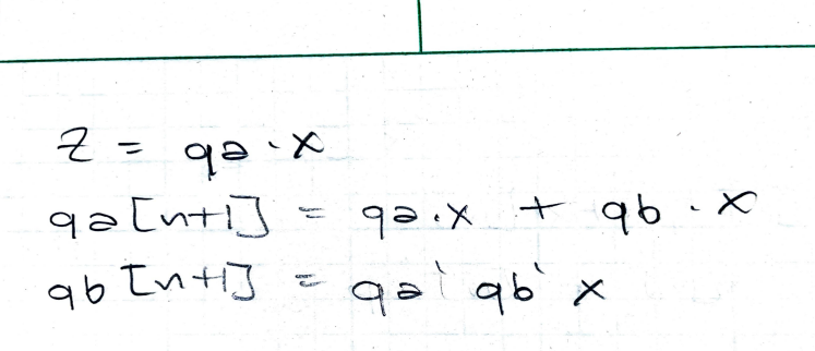 Figure 19. Logic equations of the given circuit
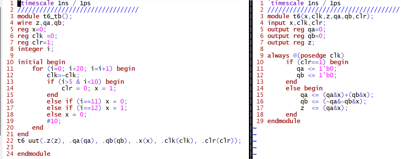 Figure 20. Gvim windows snapshot of the given circuit in task 6
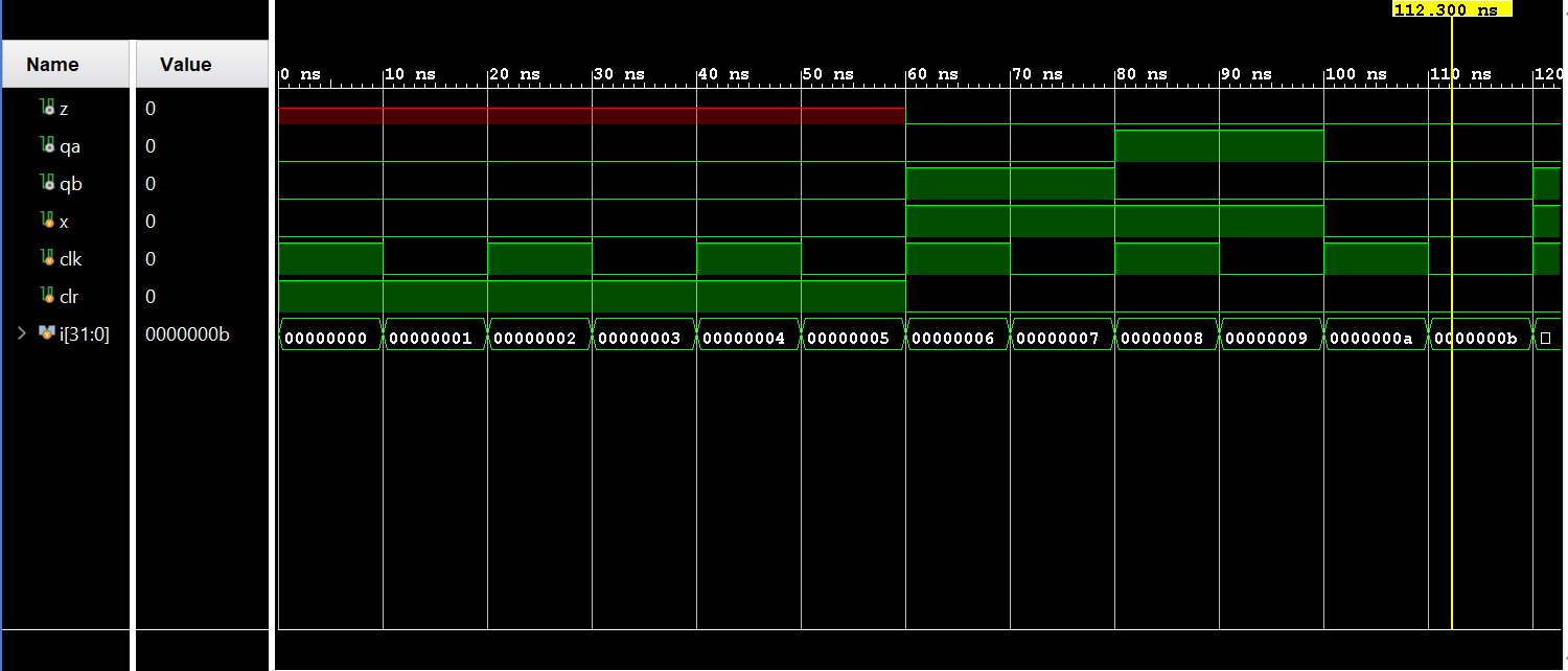 Figure 21. Vivado simulation of the given circuit in task 6