CE 433 Spring 2024
Homework 4: Data Storage
Sahra Genc
sggenc@fortlewis.edu
HOMEWORK 4: Data Storage
Task 1: Repeat the simulation in Sections 1 - 3.

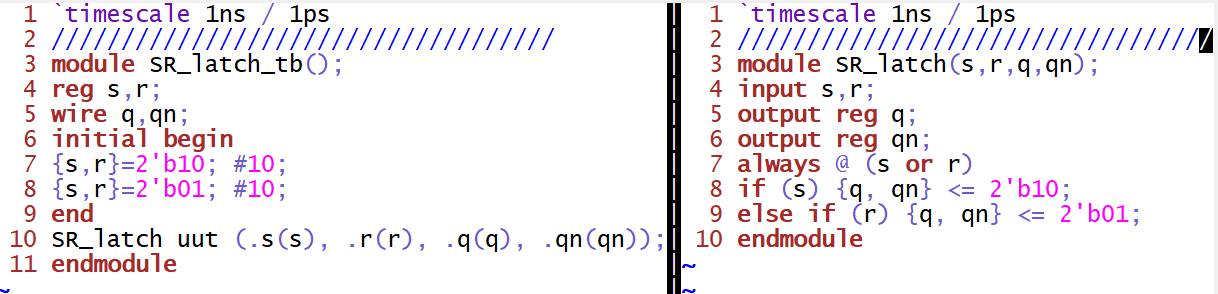
Figure 1. Gvim windows snapshot of the SR latch code implementation
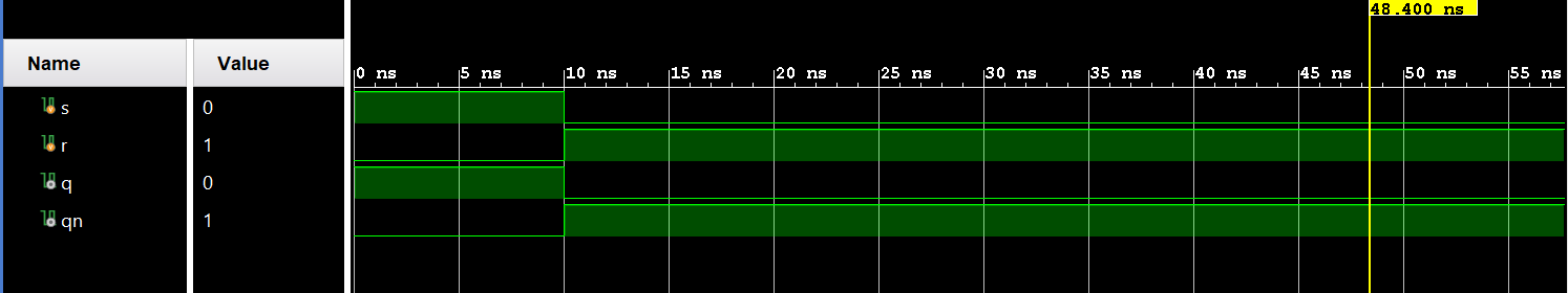
Figure 2. Vivado simulation of the SR latch
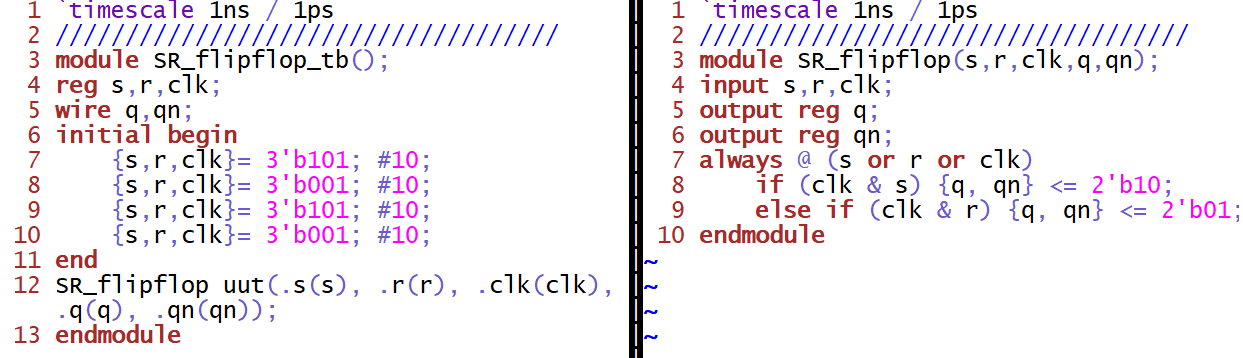
Figure 3. Gvim windows snapshot of the SR flip-flop code implementation
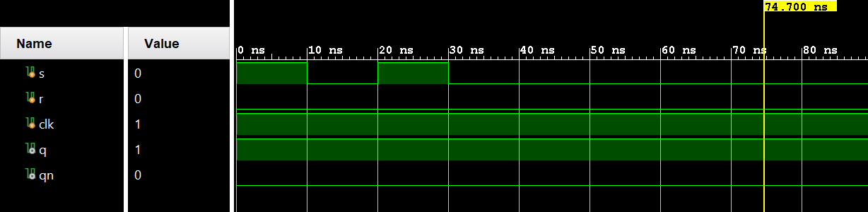
Figure 4. Vivado simulation of the SR flip-flop
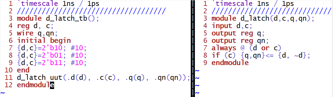
Figure 5. Gvim windows snapshot of the D latch code implementation
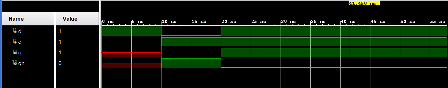
Figure 6. Vivado simulation of the D latch
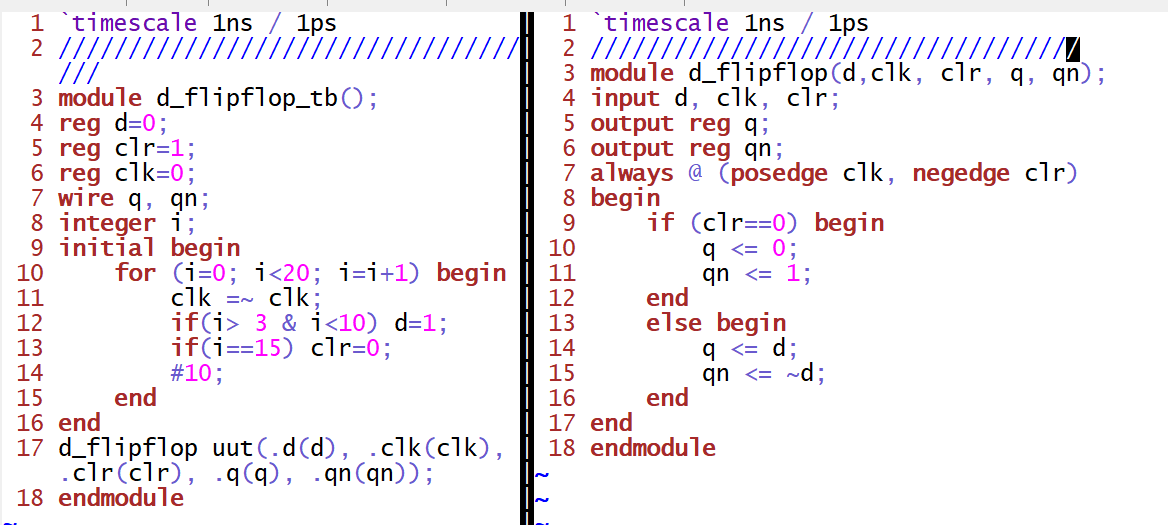
Figure 7. Gvim windows snapshot of the D flip-flop code implementation
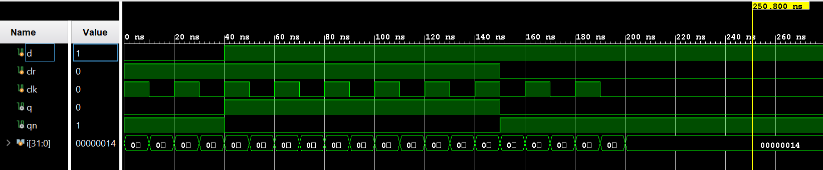
Figure 8. Vivado simulation of the D flip-flop
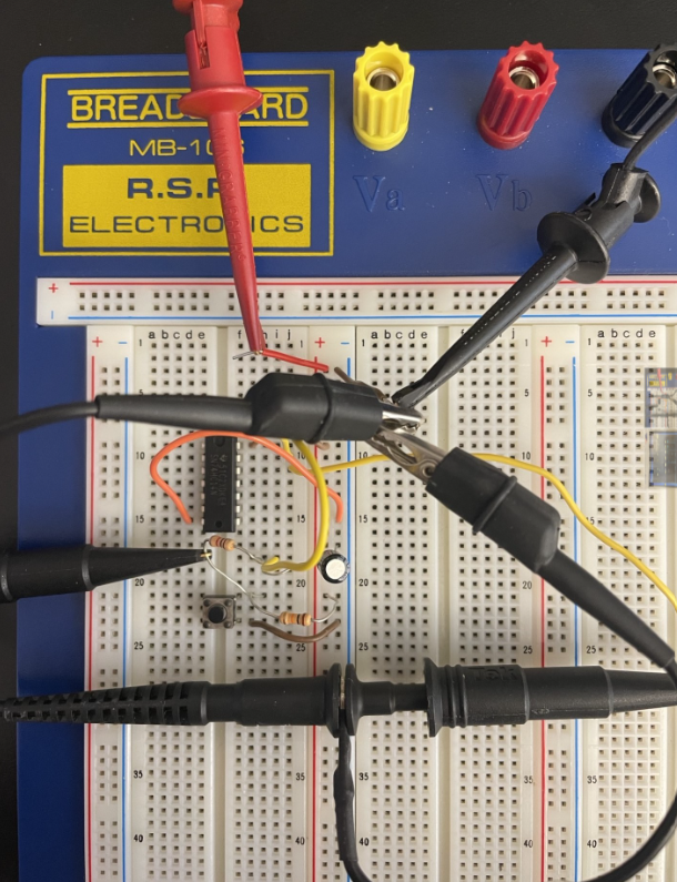
Figure 9. Breadboard set up of the debounce circuit
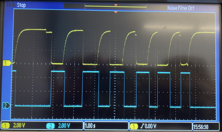
Figure 10. Illustration of the debounce circuit on the oscilloscope
Task 3: Write the testbenches and run simulations for Section 4 and Section 5.
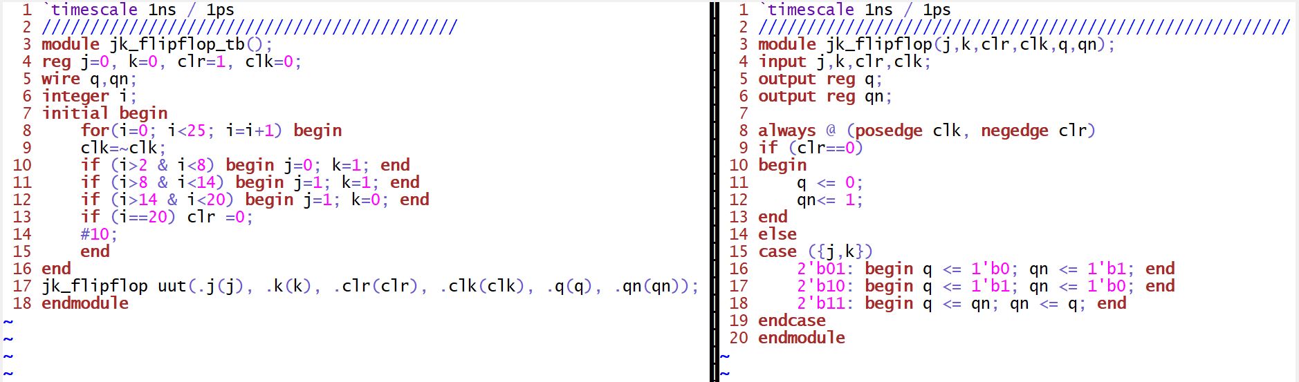
Figure 11. Gvim windows snapshot of the JK flip-flop code implementation
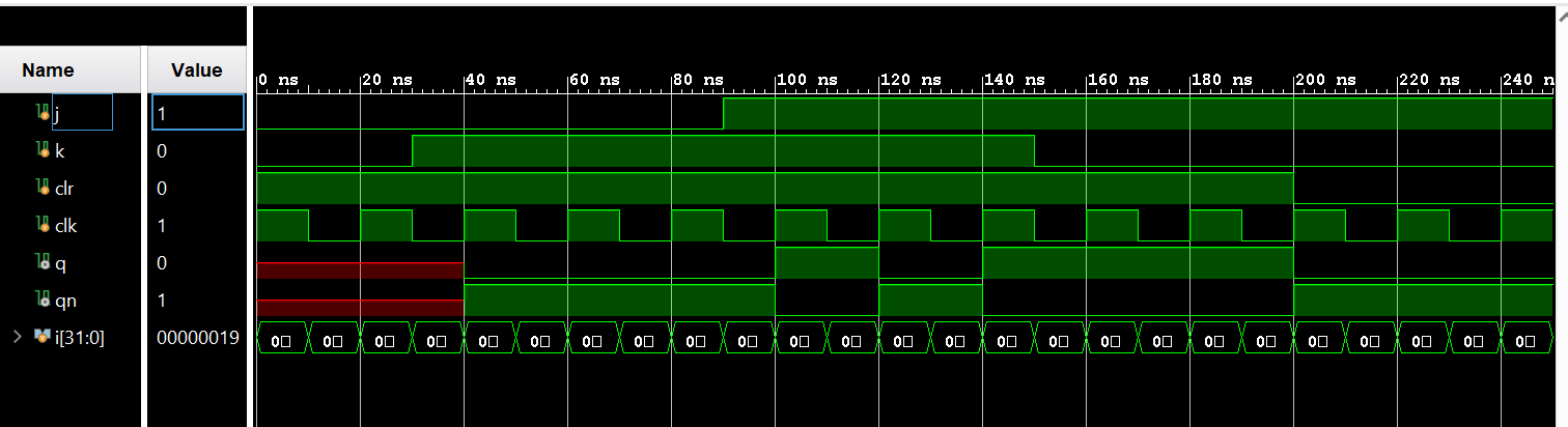
Figure 12. Vivado simulation of the JK flip-flop
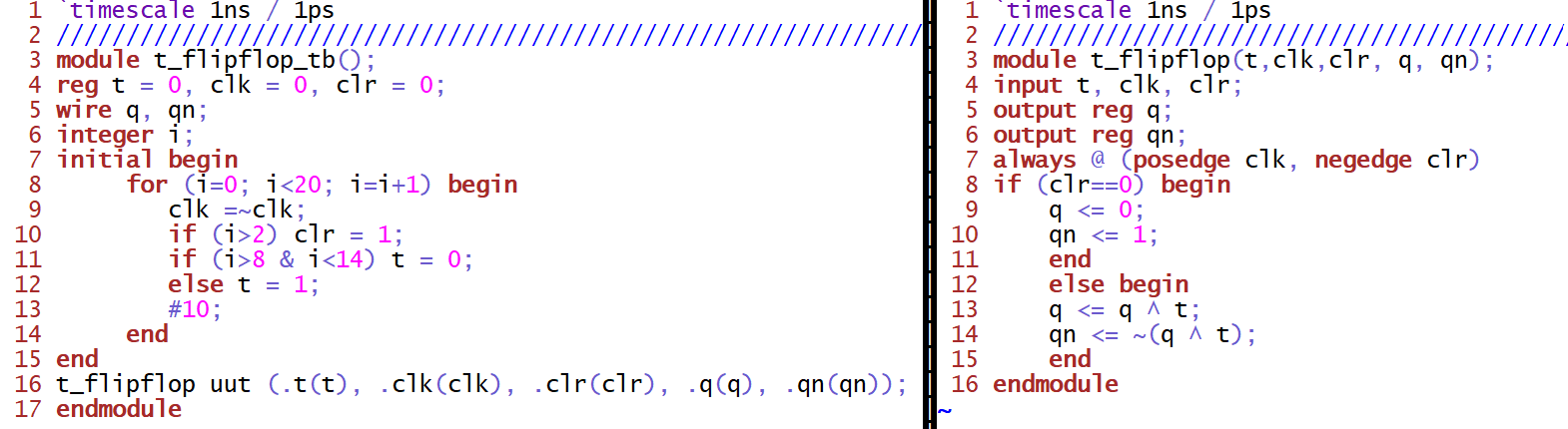
Figure 13. Gvim windows snapshot of the T flip-flop code implementation
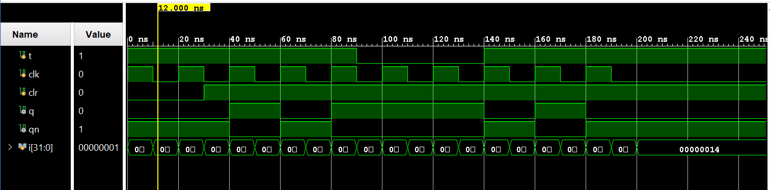
Figure 14. Vivado simulation of the T flip-flop
Task 4: Repeat all the work in Section 8 and complete the task described in the end of Section 8.
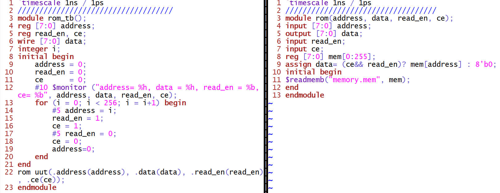 Figure 15. Gvim windows snapshot of the ROM memory code implementation
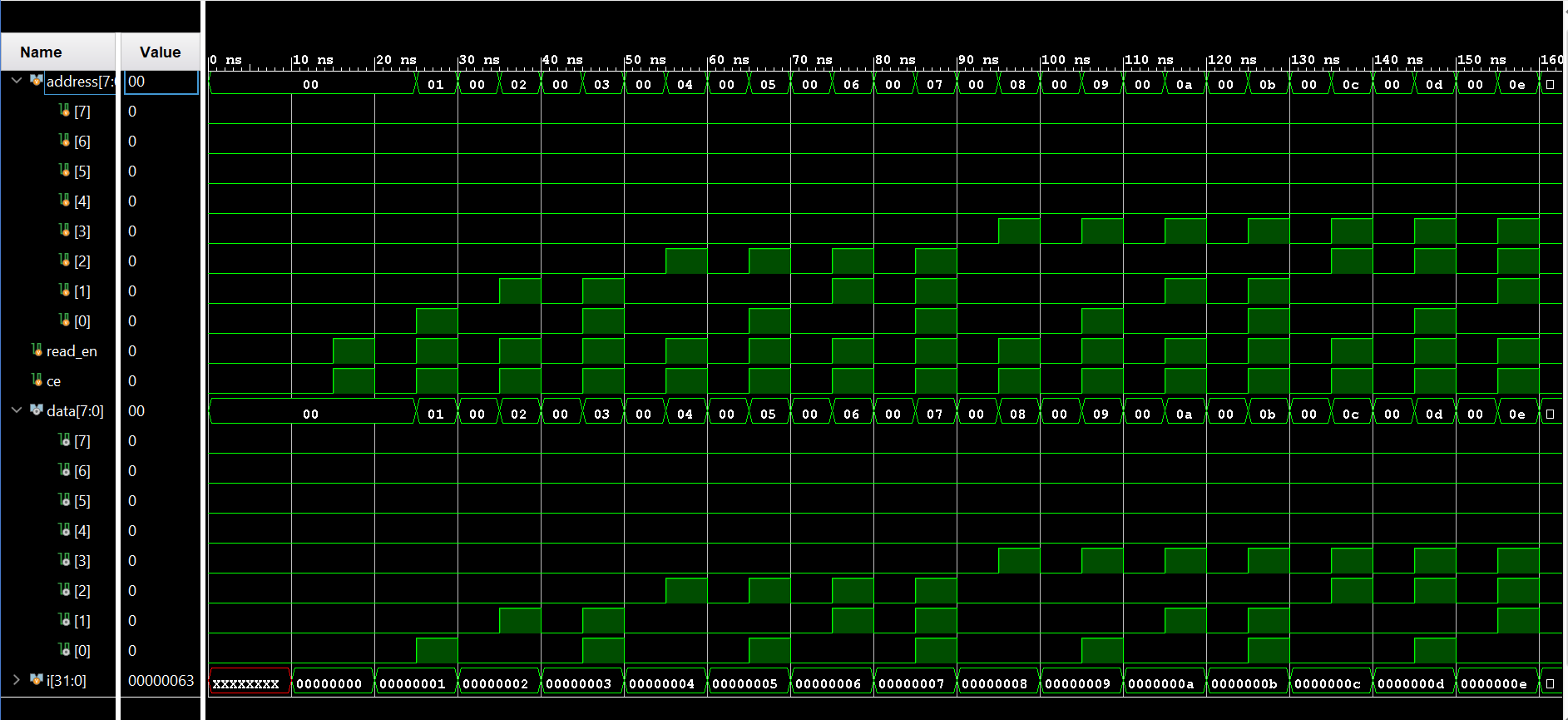
Figure 16. Vivado simulation of the ROM memory
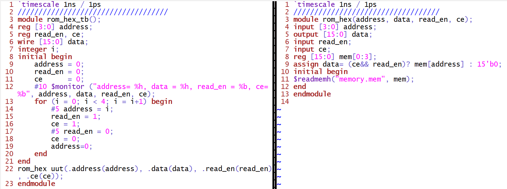
Figure 17. Gvim windows snapshot of the ROM memory using hex number code implementation
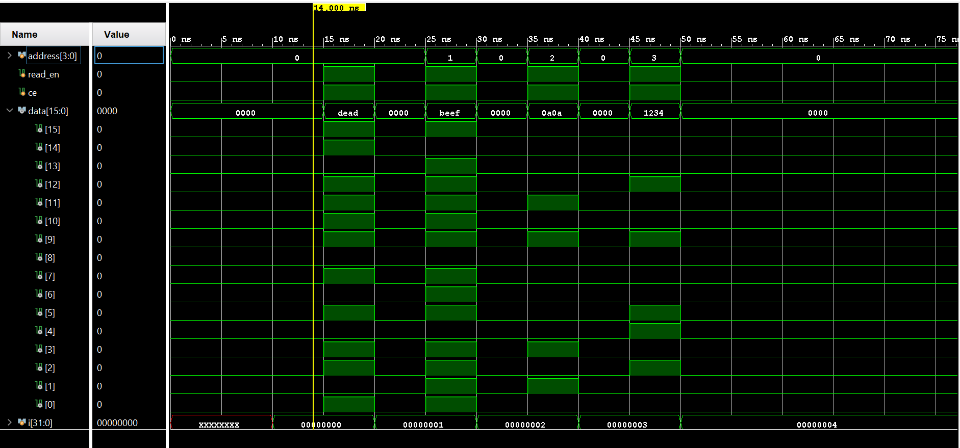
Figure 18. Vivado simulation of the ROM memory using hex number
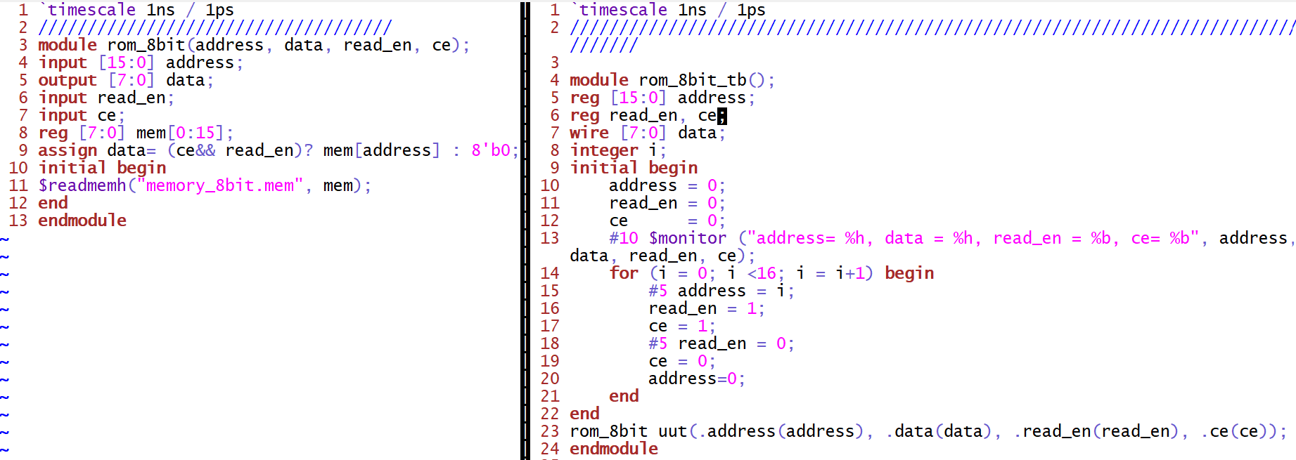
Figure 19. Gvim windows snapshot of the ROM memory using 8 bit binary code implementation
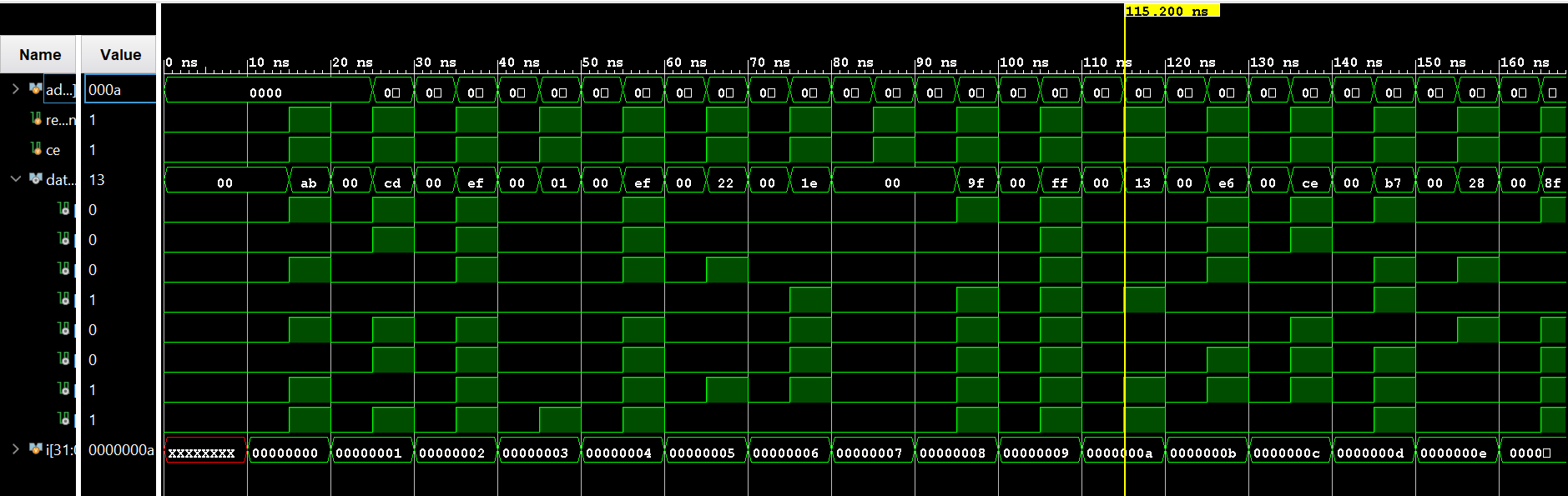
Figure 20. Vivado simulation of the ROM memory using 8 bit binary
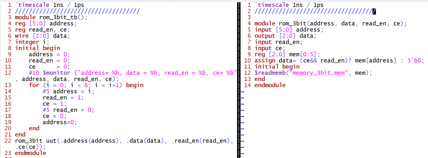
Figure 21. Gvim windows snapshot of the ROM memory using 3 bit binary code implementation
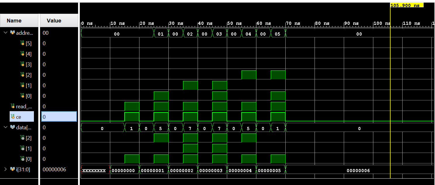
Figure 22. Vivado simulation of the ROM memory using 3 bit binary
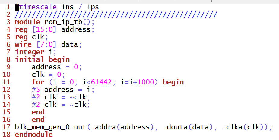 Figure 23. Gvim windows snapshot of the testbench used to extract data from the ROM IP core
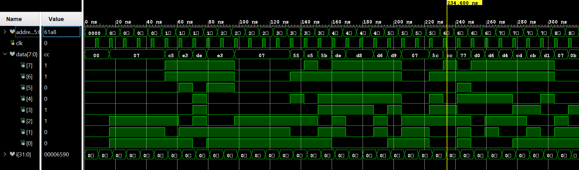
Figure 24. Vivado simulation of the extracted data from the ROM IP