Using
superposition, voltages and currents were calculated by hand shown in
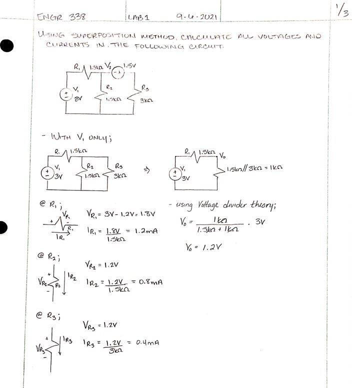
Figure 1. The original circuit schematic can be seen in the upper left
of Figure 1. Following the superposition procedure, and applying the
voltage divider theory all three voltages and currents were calculated.
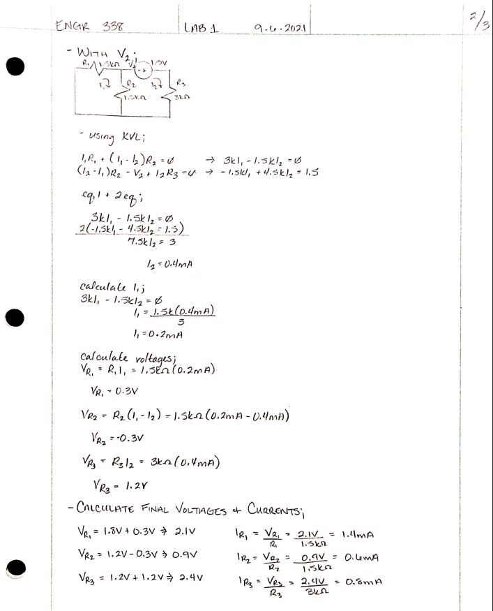
The voltage across resistor 1 or R1 was found to be 2.1 V, the voltage
across R2 was 0.9V and across R3 was 2.4V. Each of the currents were
calculated to be 1.4mA, 0.6mA and 0.8mA, respectively. All calculations
can be seen in the lower right.
Figure
1: (a): First schematic's hand calculations using superposition. (b) :
Hand calculations showing final voltage and current calculations.
As per the lab instructions, only spice code was used which can be seen in Figure 2 below. The figure also shows each of the voltages and currents, however V(1) below clearly shows a volatge of 3V, this is because the code is taking the voltage at node 1 just above the 3V voltage supply. But the current across R1 is equal to 1.4mV, from which the volatge can be calculated using Ohm's Law. As a result, all calculations have been verified using LTSpice.
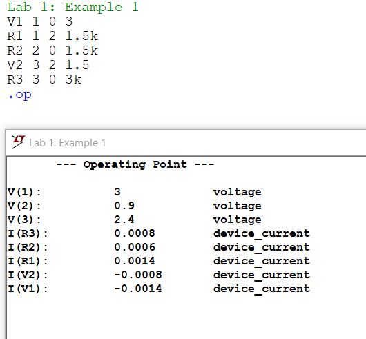
Figure 2: Calculations from LTSpice, to verify calculations.
ii. Example 2-
Using
Thevenin's equivalent circuit to simplify the schematic to an RC
circuit shown in Figure 3, below. Once simplifed the time delay was
found to be 5.6 micro-seconds.
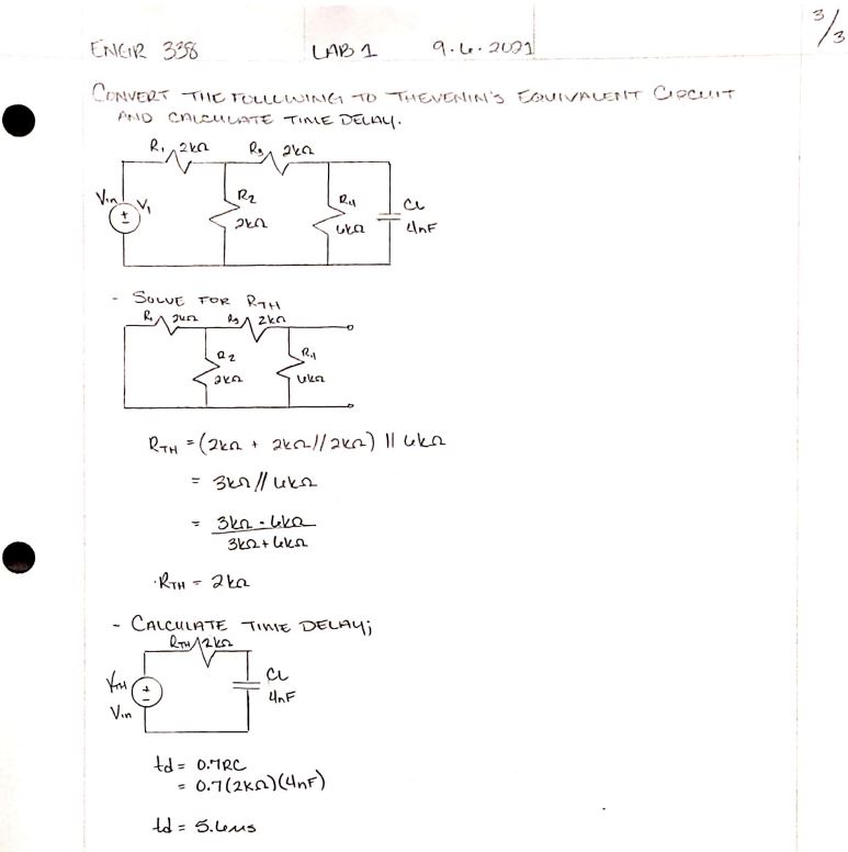
Figure 3: The hand calculations for the second schematic, which the time delay was found to equal 5.6 micro-seconds.
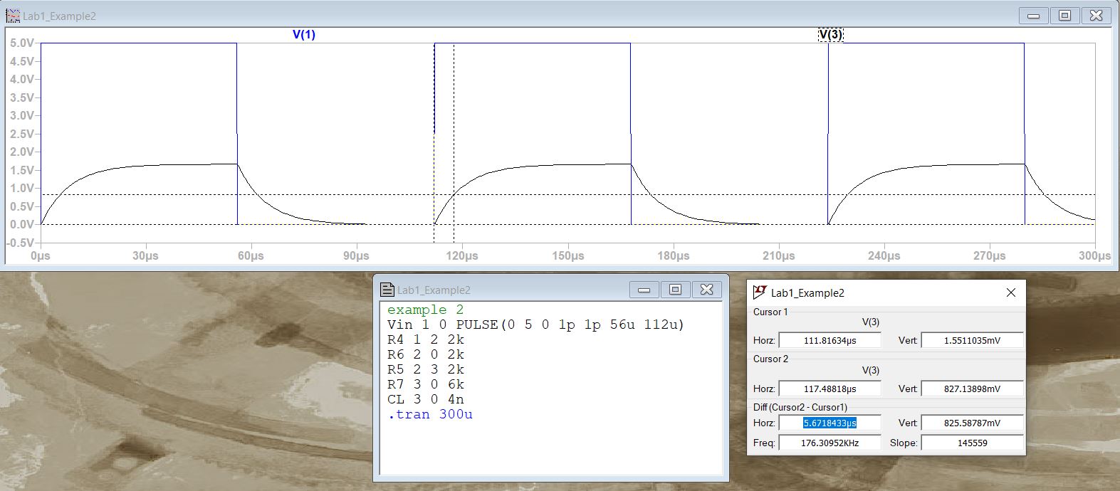
Figure
4 shows the LTSpice simulation using only the spice code, and the
difference or time delay of the circuit shown in the lower right. The
simulation showed a difference of 5.67 micro-seconds, which is
relatively close to the hand calculations result.