Homework Week
3
Noah
Smith
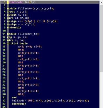
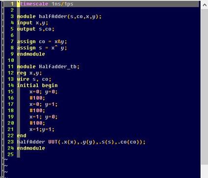
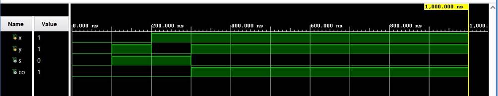
1. Repeat the simulation of Half Adder
and Full Adder in Section 1. Show the code, code explanations, and simulation
results in your report. (10 points)
Here is the
code for the full and half adder respectively. I chose to use dataflow handling
to simulate both the adder and the test bench. This could be done with a for
loop too.
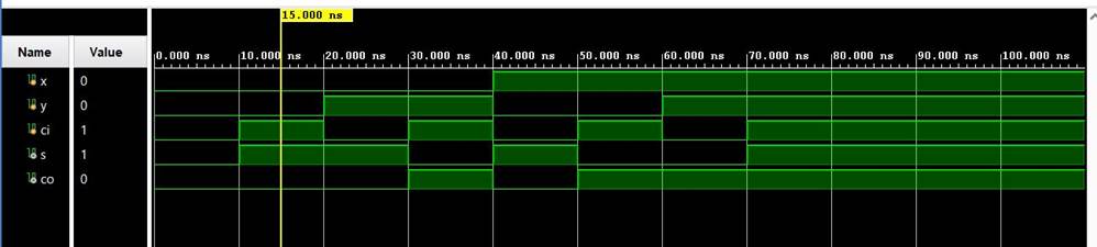
The simulation for the half and full adder are
below. ( full adder on top, half on bottom)
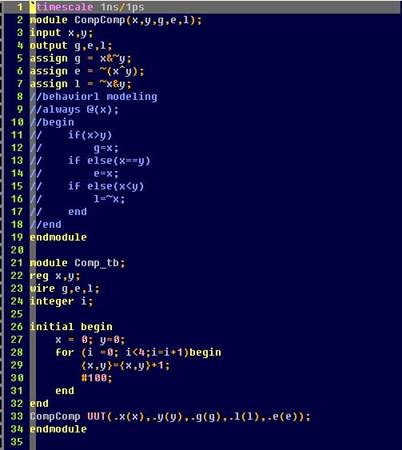
2. Design the testbench for the comparator in Section 2. Show the code, code
explanations, and simulation results in your report. (10 points)
In this section, I designed the testbench for the two bit comparator using a for loop
to iterate from 0-4 on the inputs. You can see in the simulation that the
comparator works, and is centered around the MSB.
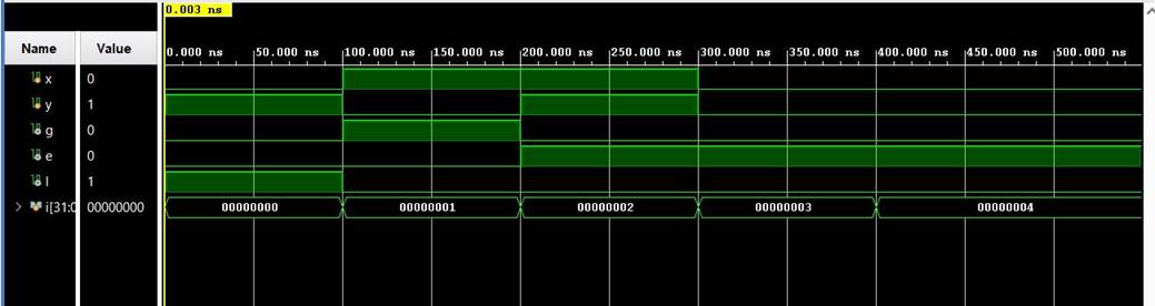
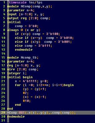
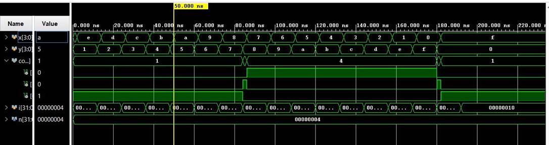
3. Design the testbench for the 4-bit comparator in Section 3. Show the code,
code explanations, and simulation results in your report. (10 points)
The same process as the 2 bit comparator
was used to design a testbench for the N bit comparator. The logic needed to be
altered slightly to accommodate the customizable size, but using behavioral modeling
and a for look this wasn’t hard. I chose to make x and
y count up and down at the same time with a slight
offset, so that all values of the comparator were explored. This can be seen
clearly in the simulation.
4. Implement a 2-bit comparator on the Basys 3 board. Use sw
as inputs and led as outputs. Show the code, code explanations, and an embedded
Youtube video demonstration in your report. (10
points)
Using the same code from above, the 2 bit
comparator was relatively easy to implement on the board. 3 LED’s
were used to show greater than, equal too, or less
than, with two switches acting as the inputs. Refer to the code above and video
demonstration below.
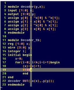
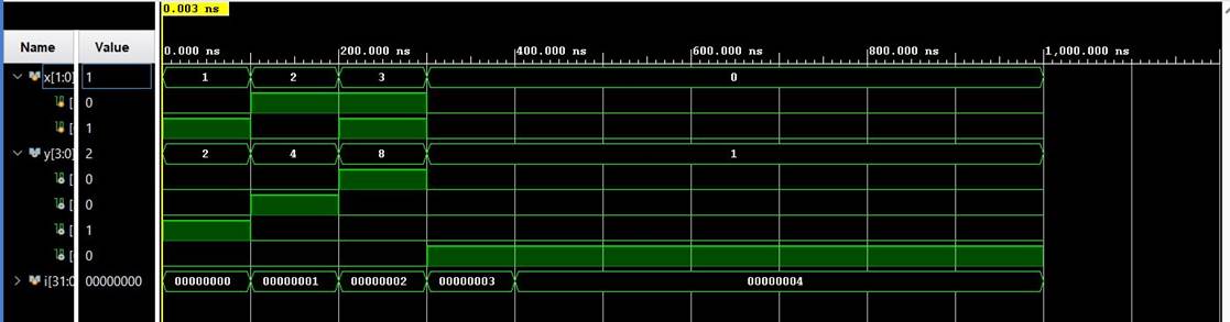
5. In Section 4, design the testbench for the decoder and verify the logic in
simulation (use the Dataflow modeling method). Show the code, code
explanations, and simulation results in your report. (10 points)
The test bench design for this decoder was simple enough,
using another for loop. Code and simulations are below.
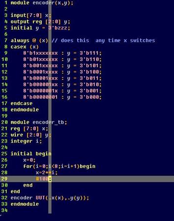
6. In Section 5, for the 8x3 priority encoder, find Q2 and Q1, build the module
and verify the logic using simulations. Show the code, code explanations, and
simulation results in your report. (10 points)
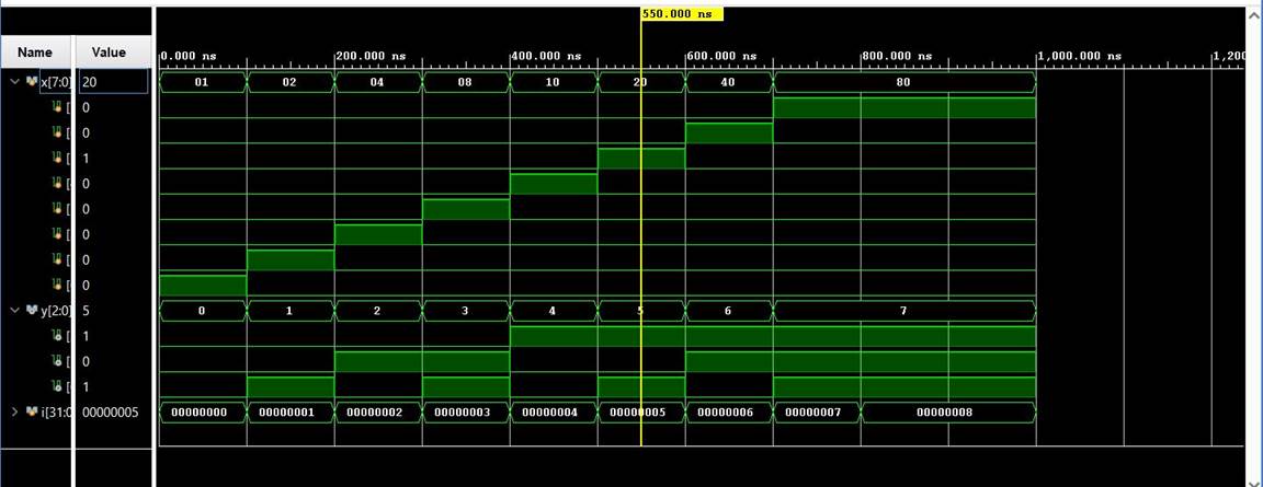
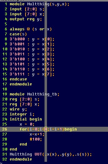
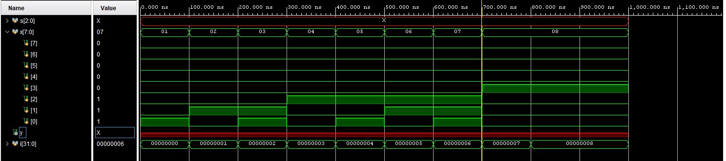
Designing a test bench for the 8x3 encoder was relatively simple
with a for loop. As you can see in the code below, each iteration
it moves the 1 down a bit by using 2i and since this is an 8 bit encoder it goes all the way to 28. The simulation
worked as planned and demonstrates the 1 moving up the 8 bits and properly encoding
into 3 bits.
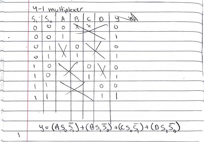
7. Derive the logic expression of a 4-1 multiplexer. Show the process on a
paper, insert it as an image into your report. (10 points)
8. In Section 6, implement a 4-1 multiplexer on your Basys 3 board. Show the
code, code explanations, and an embedded Youtube
video demonstration in your report. (10 points)
In this demonstration the 0 and 1 switches are used as S0 and
S1 respectively. I used a test input of 10101010, or only
even bits as 1. You can see in the video when counting up,
it only passes a 1 if the S0 and S1 inputs are set to pass even bits, or on an
even number.
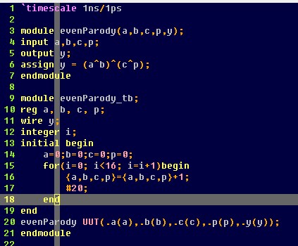
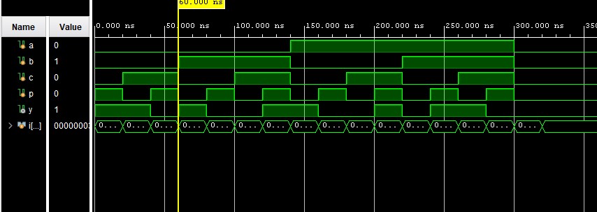
9. Design/verify an even parity generator and checker in simulation
respectively. Implement an even parity checker on your Basys 3 board - use sw as inputs, use leds as output
indicators. Show the code, code explanations, and an embedded Youtube video demonstration in your report. (10 points)
Below are the code, simulation, and demonstration of an even
parity checker. Test bench was designed with a for
loop once again, and for the demonstration, I used switches 0-3 for inputs, and
the Led as an output.
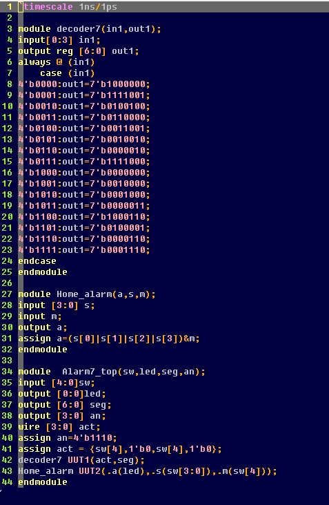
10. Implement the design in Section 8 and Section 9 on your Basys 3 board. Show
embedded Youtube video demonstration on your report.
Show the code, code explanations, and an embedded Youtube
video demonstration in your report. (10 points)
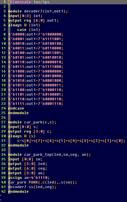
Section 8 was revamping our previous home alarm system to use
the 7 segment display. Once the 7
segment decoder was created this was a relitilvly
simple task, code and demonstration below.
Section 9 was revamping our car park code. This is essentially
a counter. We hooked this up to the 7 segment display
as well. Code and demonstration below.