SPI project
Noah Smith
The goal of
this project is to use a simulated “sensor” input analog voltage, convert it to
digital, and transmit to via SPI to Arduino and display on the serial monitor.
Our work is
to design the digital circuitry and code for the SOC that this would be
implemented on.
Step
1:
ADC
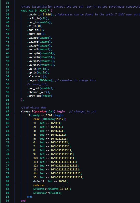
The first
step is to get the analog to digital conversion working. To do this, I used the
example code provided in the project description. I chopped everything out of
the code except for the LED indication, as it was useful for debugging and fun
to play with. It is important to note that you do need the addressing
code, either hardcode in the address or don’t delete it. I deleted it and was
very confused why
nothing worked.
Step
2:
Top
Module
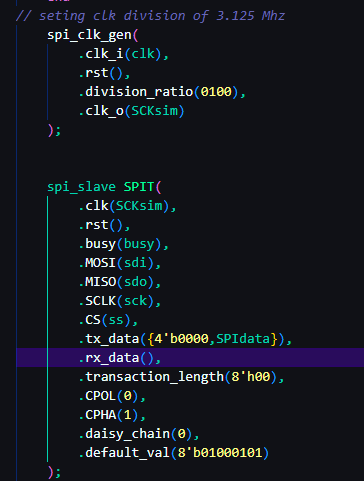
Next up is
building a top module to combine the ADC and SPI transmitter. In this project
the Arduino will be the master, and the FGPA will be the slave. So we need to use SPI slave code for it. I chose to not use
the SPI code out of the textbook and instead wrote my own, taking heavy inspiration
from this GitHub. suoglu/Simple-SPI: Set of simple modules to communicate
using SPI protocol. (github.com) This solved some issues I was having and is also just some well written
code to learn from. (I also used this clock divider to eliminate errors)
Another
important thing to note in the top module design is that the Arduino is
expecting 8 bits of data per transmission. In the example code and in my code the
4 MSBs of the ADC output code are all that is used. So
when you send the data to the SPI slave module, you either have to pad it with
0’s or pack 2 data bits into this transmission. You can see in line 84 of the
above picture that I am passing SPIdata to SPIdata1
every clk cycle. This is then concatenated with the SPIdata to form an 8 bit
transmission in the below code. We will use this packing later in the master
side of the code.
Step
3:
Hardware
For the
hardware portion of this project I wired up everything
according to the block diagram. The picture can be seen below. The SPI cable
colors are as follows. SCK-yellow, COPI-green (unnecessary), CIPO-Blue,
CS-orange.
Step
4:
Arduino
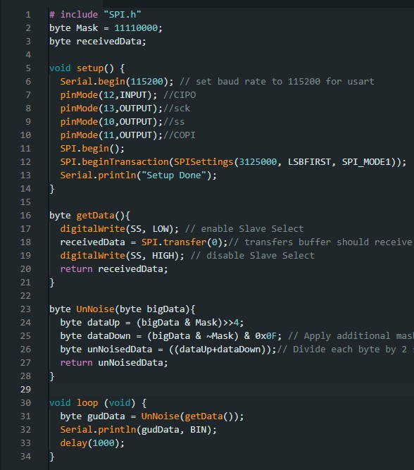
In the Arduino
code I used the SPI.h library to eliminate errors. I have
the clock set to 3.125 MHZ to match the SPI slave module. I am receiving data LSB
first. The other thing happening here is using bitmasking
to unpack the combined data bit transmitted by the slave, and
averaging the two 4 bit pieces of data.
Below
is a working demonstration.