CE433 Midterm
Noah
Smith
1. Fundamentals
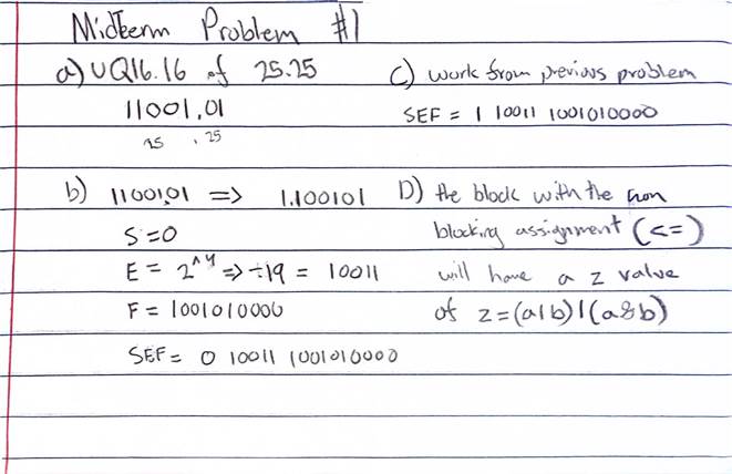
(a) Show the UQ16.16 fixed point representation of 25.25
(10). (5 points)
(b) Show the floating-point representation of 25.25 (10)
(half precision). (5 points)
(c) Show the floating-point representation of -25.25 (10)
(half precision). (5 points)
(d) Which ‘z’ has the new x and y values if the following
two blocks are being executed separately and only once? (5 points)
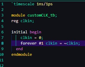
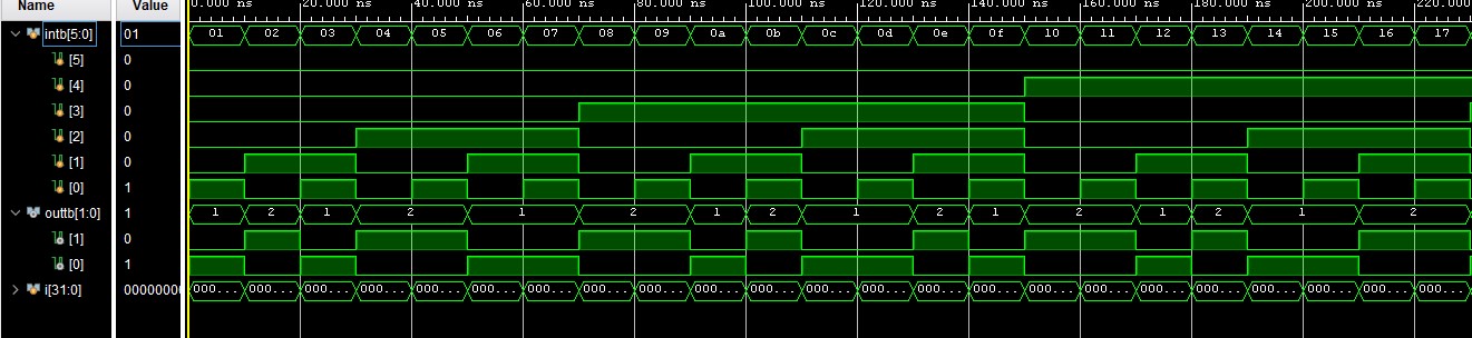
2. Make a
2 ns period clock waveform. Show the code and the simulation results for
credits. (10 points)

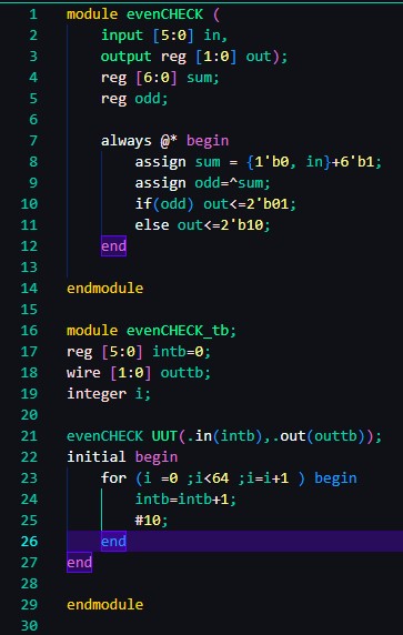
3. Design
a module which has a 6-bit input bus. The module checks if there are even
number of one’s or odd number of one’s in the input. The two output bits shows output =2’b10 when it’s even, shows output = 2’b01
when it’s odd. Show simulation results that displays
both outputs. (10 points
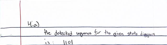
4. (a)
Given that the following state diagram is a sequence detector. What the
sequence of 4-bit binary code it detects? (10 points)
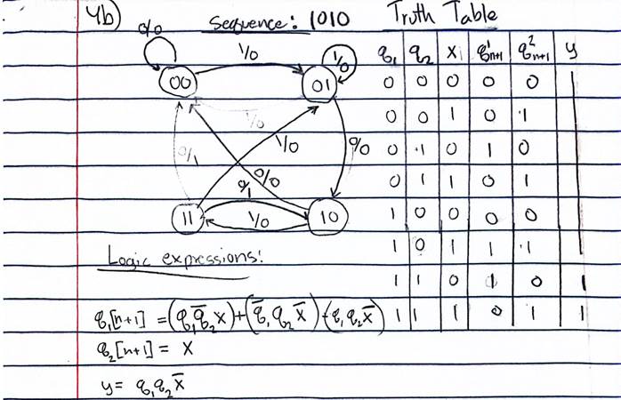
(b)
Design a sequence detector to detect a serial input of 1010 by completing the
following tasks: (50 points, demonstration video required)
•
Draw the state diagram similar to what is shown
in (a). (10 points)
•
Find the truth table of the sequential circuit. (10 points)
•
Find the logic expressions of the sequential circuit. (10 points)
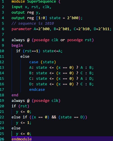
•
Code it up using the behavioral Verilog model. (10 points)
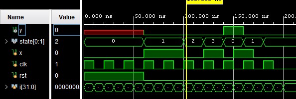
To code this up in Verilog
I used a similar format to the other sequencer we made in a pervious homework assignment.
I chose to use one case statement and the ? operator to
set the logic. You can see a brief simulation I did to check the sequencer
logic before moving onto the next part.
•
Implement it on the Basys 3 board. The serial input must be taken by a
switch, the values of the switch are registered by another switch (as a clock).
When the sequence is correct, the monitor shows a solid green color (through
VGA). When the sequence is wrong, it returns to a solid red color. Continuous
inputs are allowed which means the customer is allowed to keep registering code
into it and whenever 4’b1010 is detected, it turns green otherwise, it turns
red. (10 points)
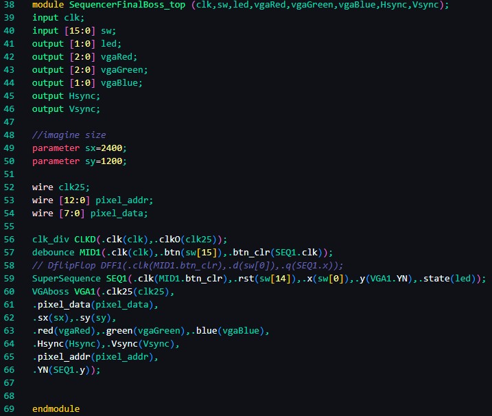
Below is the code for the top module used to achieve the above
behavior. The debounce and clk_div module are simple
modules that have been used previously. The VGA module used is an exact copy of
one used in previous assignments, the only change was the inclusion of a YN
variable. This is tied to the output of the sequencer. If this is 1 is sets the
RGB value to Green, otherwise it is red. In order to
get this code to work I needed to skip the DFF module that was included in the
block diagram. This was blocking the sequencer from reaching state C or 10.
With this removed you can see that the entire system works as desired in the
video below. The LED’s are used to indicate the binary
state, this was implemented as a debugging method to help with error checking.