LAB 3
Noah Smith
In the last lab we created an
DAC in Electric VLSI. This can be seen below.
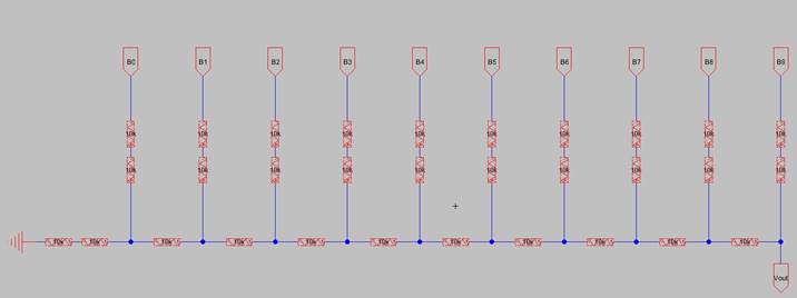
In this ladder we use a bunch of repeated segments
of resistors. This can be made easier in the future by creating an icon for
these groups of resistors. That is what we will be doing in this lab.
Task 1:
Create the schematic of the subcells for the R-2R
ladder.
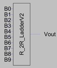
First, we copied the repeated part of the
ladder into a new schematic and then created an icon from that schematic. Seen
below.
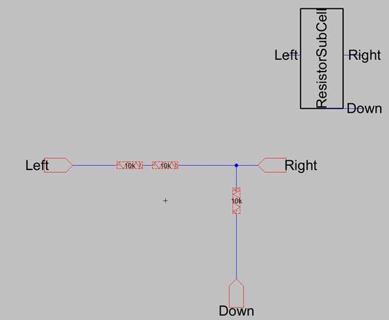
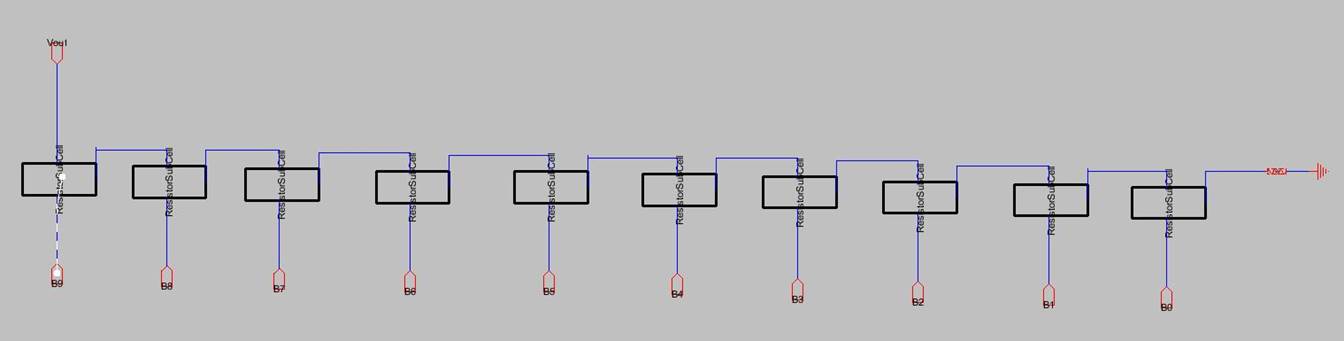
Now that we have this icon created, we want to
recreate the ladder ADC from the last lab, but with our new icon to simplify
things.
Troubleshooting errors while
creating ladder:
-While right/left
clicking wires into place, keep an eye on the errors tab of the file explorer.
This will allow you to spot DRC errors before running DRC and fix them
immediately.
-Watch for hanging
wires. These will cause an error, and sometimes get created from getting
trigger happy on the wire creation clicking.
Once the DRC clears, we need to create an icon
for this DAC just like we did for the repeated part of the ladder.
Task 2:
Create the layout of the subcells for the R-2R
ladder.
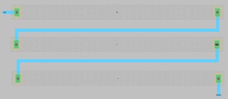
We now need to make the subcell
from task 1 with n-well resistors. We start this by creating a layout of the subcell and dragging an N-Well resistor from the left menu
x3.
Give each N-Well resistor the properties:
Length=187.5 Width=15 and resistance of 10k.
Next wire the N well resistors as seen below.
Be sure to export nets just like a normal schematic.
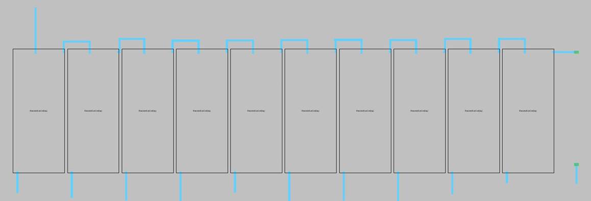
Next we will create the layout view for the ladder (DAC). This is
done the same way as above, but now, drag the subcell
in from its layout. Just as you would an icon into a new schematic.
Now we want to use the very useful “Array”
tool. (This can be found in the edit dropdown) Space your array of 10 subcells so they don’t overlap.
Be sure to wire these together. Use them the
same way you used the subcell icon earlier. Be sure
to export nets as the appropriate labels!
Be sure to run this through NCC. (The error
messages it provides when it fails are useful.)
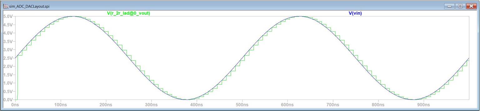
Finally we need to plug our new and improved ladder into the original
ADC simulation. Wire the B plugs to themselves just like the previous lab.
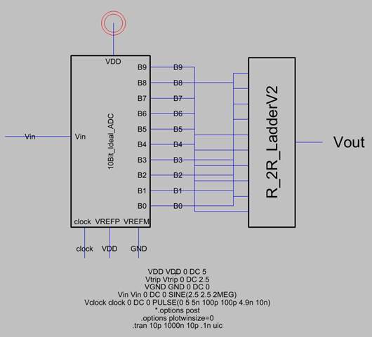
Finally we need to simulate using spice to check that we did everything
correct!