LAB 7:
LCD Display
Noah Smith
The goal of this lab is to use the Basys 3 board to interface with an LCD
display.
Task 1: Repeat work from textbook.
This task was to display various words
on the LCD display based on the input from switches. The wiring description can
be found in the textbook. **REMEMBER TO GROUND THE BASYS 3 BOARD**
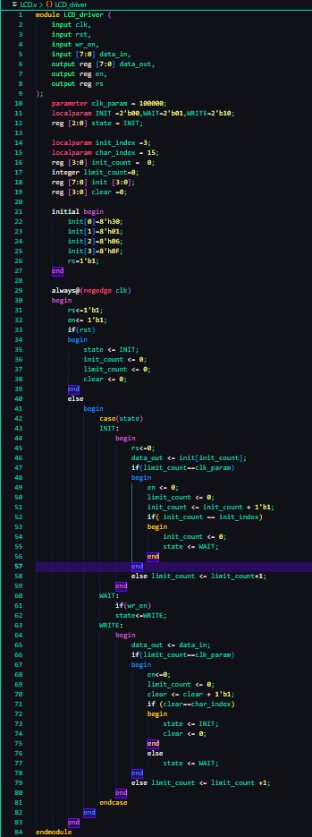
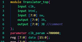
This consisted of two parts: the LCD
driver, copied directly from the textbook, and the translator module, which I
had to modify to work for our applications. The code for the LCD driver and
modified Translator module can be seen below along with a demonstration video.
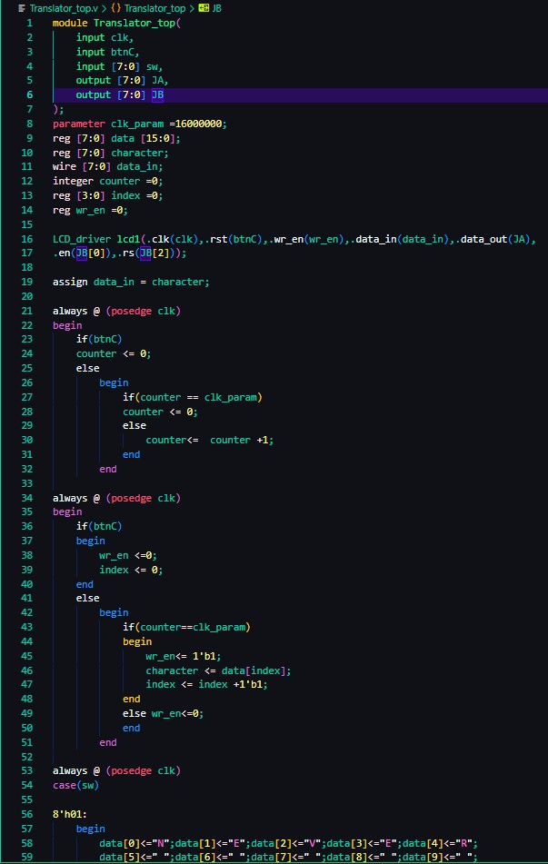
Modifications:
Modifications to the translator module
involved:
o Adding switches
as inputs
o Replacing “data_out” with JA[0:7]. These are pins
on the Basys 3 board we used for the LCD write data.
o Replacing
enable and Rs pins with JB0 and JB2.
With these modifications to the
translator module the LCD will run off the Basys 3 board.
Task 2: Make the words steady
In order to make the
words steady on the screen we needed to decrease the display time from 16000000
to 700000, this makes the refresh rate fast enough that it looks like the word just
displayed.
The code modification in the
translator module can be seen below as well as a demonstration video.
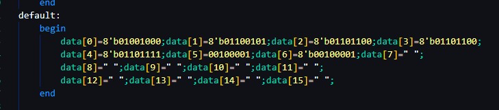
Task 3: Use ASCII code instead of
characters
This is a simiple matter of consulting
an ASCII table and replacing the character maps with the binary ascii values. I
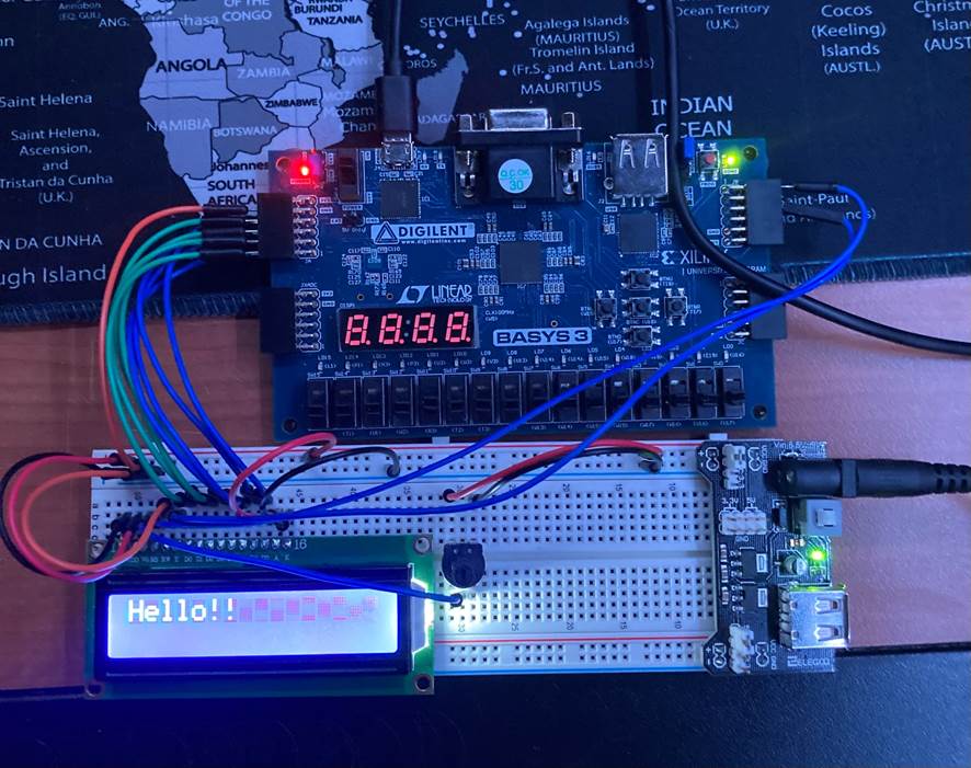
chose to modify the default state of my translator module. The modified code seen below. There is also a picture of completed wiring and “HELLO!!”
being displayed.