LAB 4: Traffic Lights
Noah Smith
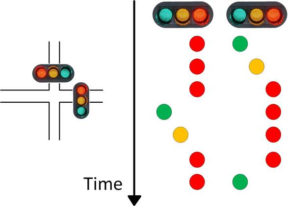
The goal of this lab was to simulate the logic
of a pair of traffic lights seen below:
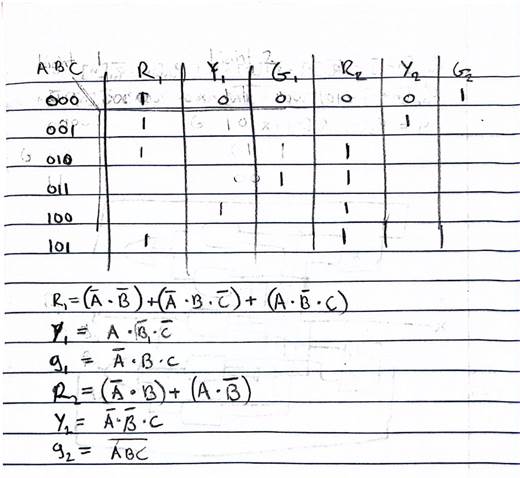
I started this process by looking at the whole system and
simplifying the truth table and deriving logic equations from it. The truth table in the above diagram has
several repeat states and I chose to simplify this from 7 states to 6 and map
it to a state variable. This choice will be useful when creating the rush hour
mode later. This is a 3 bit binary number seen on the
left side of my truth table. I have it denoted as A B C for the 3 bits, this
makes finding the logic equations “easier”. Below are the 6 logic equations for
each Red, Yellow and Green light.
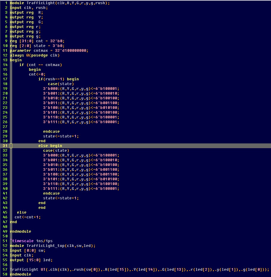
Now that we have the logic and truth table worked out we need to
code it in Verilog. As you can see in the code below I
chose to use case statements to define the logic. I use a 3
bit State variable that counts up every 1 second to control the lights. The
“Normal “ mode is the bottom case statement. After implementing
an even cycle ignoring the 2 unused states I chose to
modify the case statement and gave each green light 2 clock cycles instead of
1, because it made more sense, as this is closer to how traffic lights operate normally.
Rush Hour:
To implement rush hour mode I used
one of the switches. If the switch is flipped then the code goes into the upper case statement. In this case statement I gave 1 greenlight cycle
3 clock cycles and the other one just 1. This makes the greenlight on the “busy”
road stay on 3x longer. This is done simply by shuffling
the spare states around.
Video demonstration is below. One light is on the left 3
LEDs and the other light is on the right 3 LEDs. The rush hour switch is switch[0]. I demonstrate both the normal and rush hour modes
in the same video.