ENGR338 Lab 2022
Fall
Lab 9 8-bit ALU
Name: Mason
Brady
Email:
mrbrady1@fortlewis.edu
8 Bit ALU
Introduction:
This lab uses Electric VLSI and LTSpice to simulate a combination of
gates created in the past to sucessfully create and 8-bit ALU.
Materials:
LTSpice, Electric VLSI
Methods:
First, I went to create the schematic for the ALU and as Dr. Li, I
didn't have an 8-bit inverter. I added busses and created an array of 8
inverters in the layout before creating the ALU schematic which can be
seen below in Figure 1.
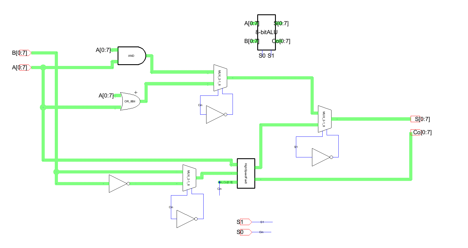
Figure 1.
8-bit ALU layout.
Since it was 8-bit everything was done using buses except for the
select pins on the MUX since the same signal goes to all 8 MUX gates.
The first signal on the full adder's carry in is the first select
signal because you have to add one to the inverted signal in order for
it to be subtraction. The top MUX is also on the S0 signal so when S1
is toggeled, there is and or functionality. All of the logic was
verified and is in the results section.
Finally, the ALU was laid out. This process seems daunting but when
approached in sections is not too bad. The main idea is to keep
everything in nice lines so that you don't cross anything and it is
easy to keep track of where each connection goes. I tried my best at
this but I chose to lay my ALU out without looking at the given one. I
ended up putting a lot of my gates vertically because I thought it made
the connections easier. The layout can be seen below in figure 2.
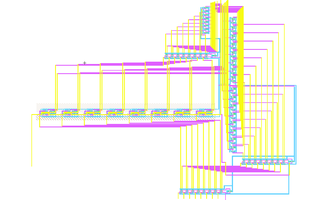
Figure 2. Overall
view of the layout
In hindsight I should've put the full adder vertically but I thought it
would make the connections easier with this layout. It ended up working
out pretty well and went surprisingly smoothly.
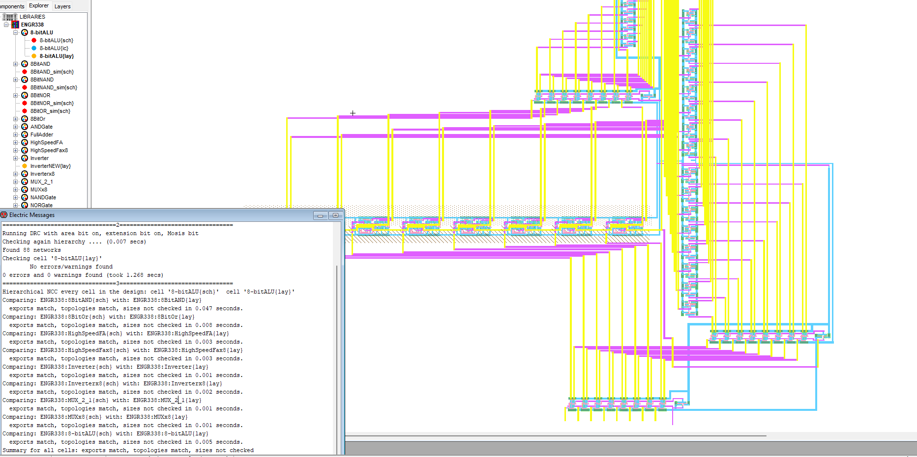
Figure 3. NCC check
and DRC.
Results:
The
first simulation was to verify the and gate by getting all 0s from
11111111 and 00000000
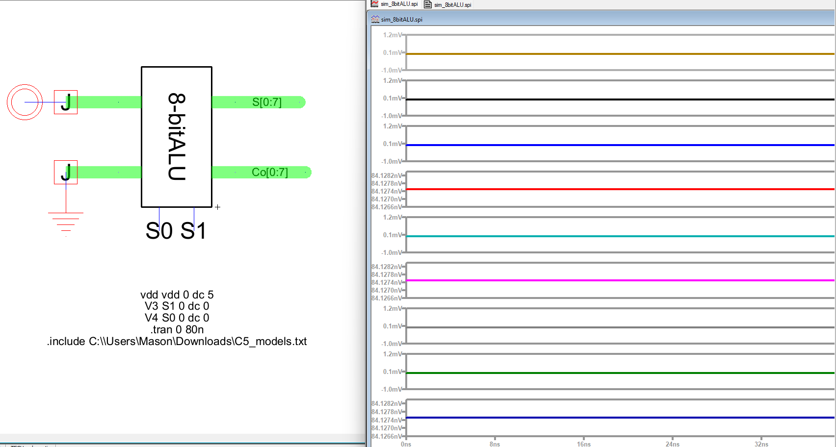
Figure 4. 8-bit
ALU and simulation.
Next, the OR gate was tested by using 11111111 and 00000000 and 1 0 for
S0, S1
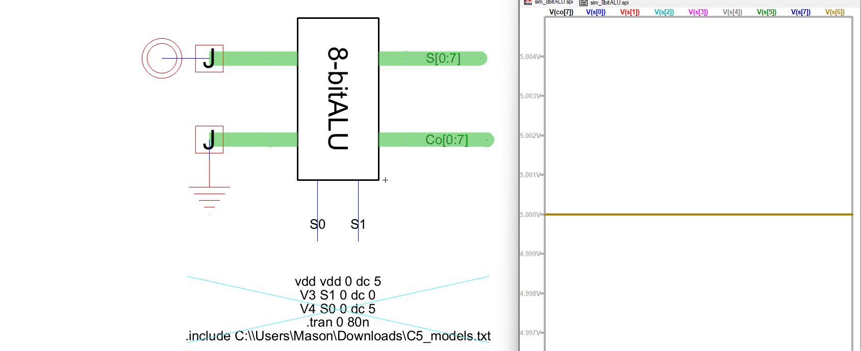
Figure 5. Simulation
of OR gate in 8-bit ALU.
Next the ADD operation was tested using 11111111 and 10000000 to get
00000000 and 1
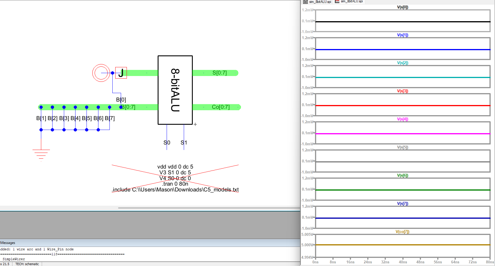
Figure 6.
Addition using 8-bit ALU.
Finally, subtraction was tested using the same numbers as above in
Figure 6. to get 11111110
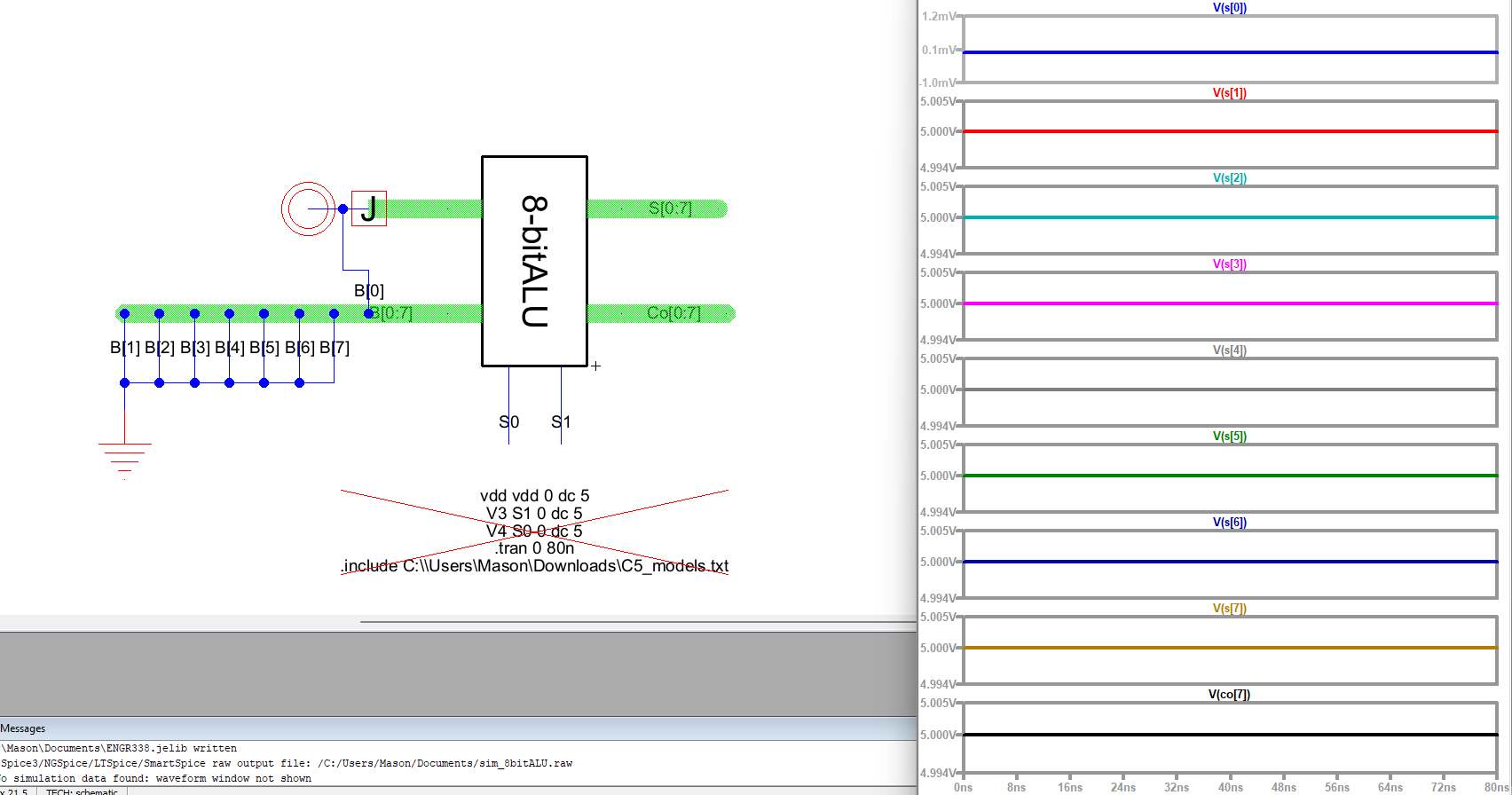
Figure 7. Subtraction
using 8-bit ALU.
Discussion: This
lab was probably my favorite. I feel like I learned a lot more about
being efficient in electric than I did in all the other labs. Learning
small thing like if you click on a metal 2 wire with a metal 3 wire
made a via automatically made a big difference in speed.