Materials: Eagle
Methods: All the nescesary footprints were generated and the schematics were all borrowed from sparkfun components. I created all of the footprints in mil on accident and had to go back through and recreate them when I got to the layout step in mm. The schematic was then created by merging the two schematics given in the tutorial to get the resulting schematic seen below in Figure 1.
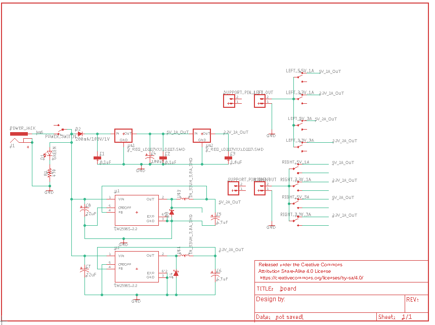
Figure 1. Schematic of Power Regulator
The layout was then generated as seen below in Figure 2 after using autoroute with 40mil traces.
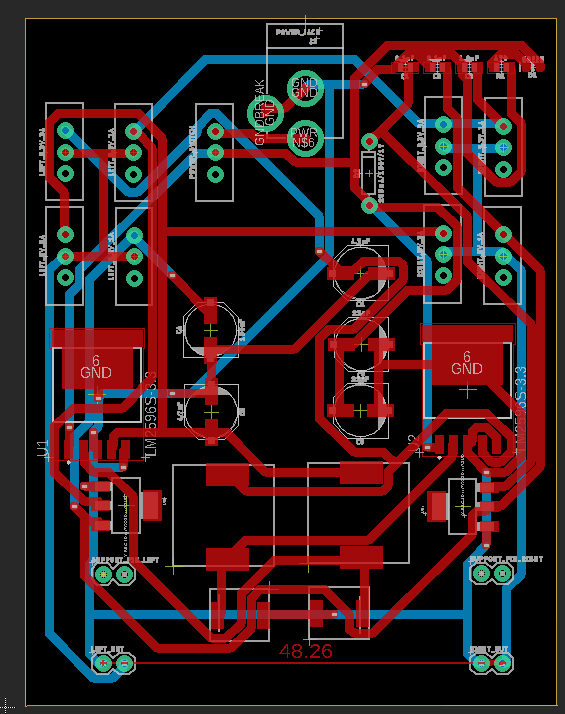
Figure 2. PCB before pouring copper.
The DRC was then checked and clear so the copper was poured on the top and bottom. The final PCB can be seen below in Figure 3.
