Embedded Systems
Spring 2024
Lab 5 Traffic Light
Name: Mason
Brady Email:
mrbrady1@fortlewis.edu
Traffic
Light
Introduction:
This lab was to learn how to do the full development work flow from
problem to programmed FPGA Materials
GVIM, Vivado, Basys 3 Methods / Results:
1) 2 Way Traffic Light
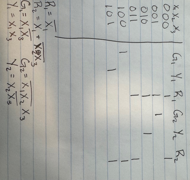
I started by creating the truth table for the traffic lights. The
trickiest part here was choosing the ideal 0 state which I think is
when both are red this seemed to simplify my logic slightly better than
the other variations I tried but their might be a better starting
point. From this the logic expressions were pretty easy to find except
for R2 because it has a nifty XNOR gate which was cool to see. It seems
like theres a lot of right answers depending where you start but using
this setup I didn't need a kmap since they were super easy and they
only ones that required thought were the reds. Figure 1. Hand
Calculations for Logic Statements for Traffic Lights.
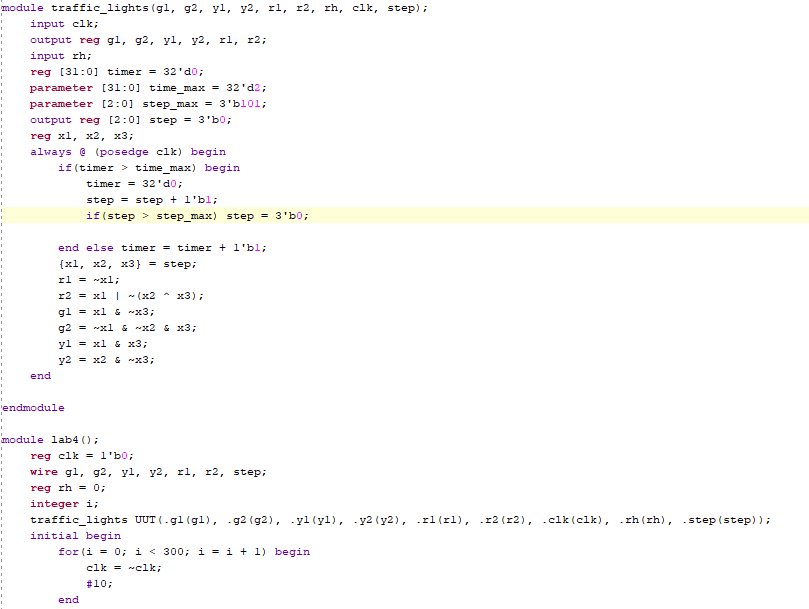
From this the code was fairly straightforward. Some of the parameters
can be ignored for this part since I was just future proofing it for
step two so I wouldn't have to rewrite anything (rh is the rushour
enable). The code is fairly simple I think there is a better way of
using the step count instead of breaking it up every loop but this
worked out fine. Basically if the clock has reached the loop limit (2
for simulation and 50000000 for the Basys) then it increments the step
in the loop and resets the timer. The step count is then used for the
logic expressions above by just breaking it into it's individual bits
and using the aformentioned logic. The simulation results are as
expected. I found out that you can rearrange signals in the viewer
which was nice to know especially for this project it made it much
easier to read. Figure 2. Simulation
and HDL code for Two Way Traffic Light.
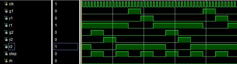
2) Rush hour I didn't have to change much with my code for this to work
just implemented the rush hour switch into a second if statement which
looks for rush hour and state 100 and if these are true it uses a
second timer maximum to double the time. Otherwise the code is identical Figure 3.
Rush Hour Modification
For the on board demonstration I only took one video demonstrating with
and without the rush hour switch, it seemed silly to take and upload
two videos of the exact same thing with one just slightly different.
The video demonstrating both modes can be seen below
Discussion: This
lab was great! This was the first time I have written HDL and it just
worked. The only thing I had to debug for this entire lab was my timer
being too short and not clicking program device and wondering why it
wasn't working.