Embedded Systems
Spring 2024
Lab 3 Seven Segment Display on An FPGA
Name: Mason
Brady Email:
mrbrady1@fortlewis.edu
SSD
Introduction:
This lab was to learn how to use vivado to upload HDL to an FPGA device
to use the Seven Segment Display Materials
GVIM, Vivado, Basys 3 Methods / Results:
Tasks 1
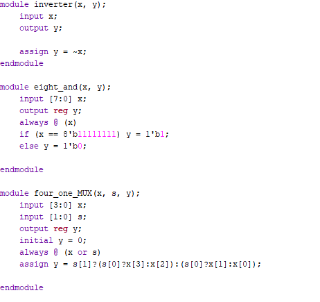
For this task we just had to make a bunch of simple logic gates and
various other basics. I wrote the big and gate Figure 1 shows the
modules for the inverter, MUX, and the big AND gate. The only one of
these that really needs explaining is the 4:1 MUX which uses conditions
to set the output in a single line. Basically if S[1] is high then it
will select the first option and second if not. Figure 1. Inverter,
8-bit AND, and 4:1 MUX Logic Modules.
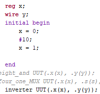
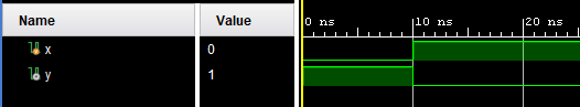
The inverter TB was easy, just flip X once and make sure the logic is
inversed Figure 2. TB
and Simulation of Inverter.
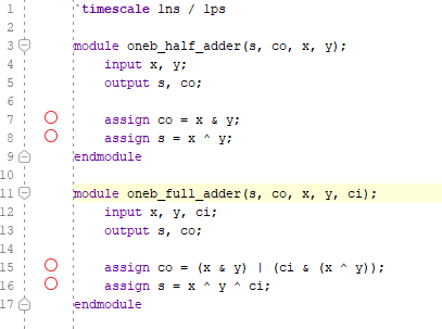
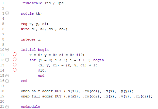
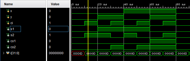
2-Bit FA and Half adder were simulated together to speed up the
process. The modules are fairly similar with the full adder just being
two half adders. The TB just incremented the concantenation of x, y,
and ci from 000 to 111 and was an easy way to test the logic for both
gates. Figure 4. Full
adder (and half adder) simulation, the output for the FA is S2 and Co2.
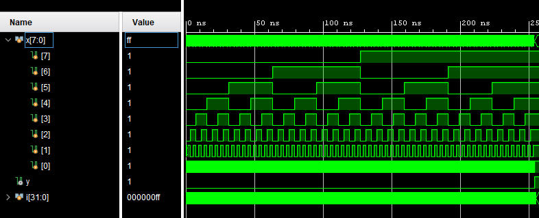
8-bit AND gate TB was written and was fairly similar to other TB in the
HW where x is just incremented to 11111111 to verify every logic
position. Y is only triggered at 11111111 at the very end. Figure 5. TB
and Simulation of an 8-bit AND gate.
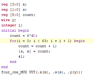
4-1 MUX TB was nearly identical to the 8-bit and I just
used a counter before concatenating to keep the code clean and easy to
read. Figure 6. TB
and Simulation for 4:1 MUX.
Task 2
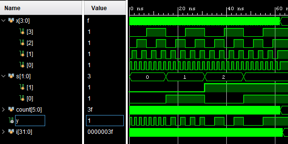
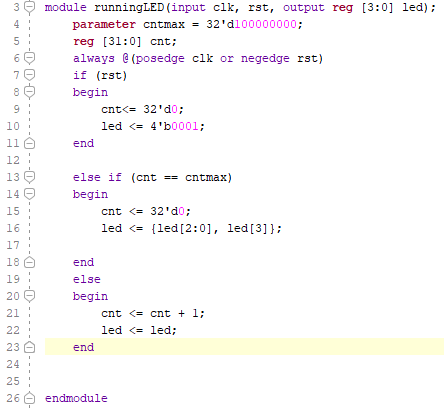
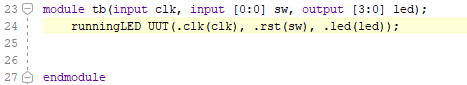
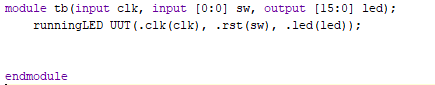
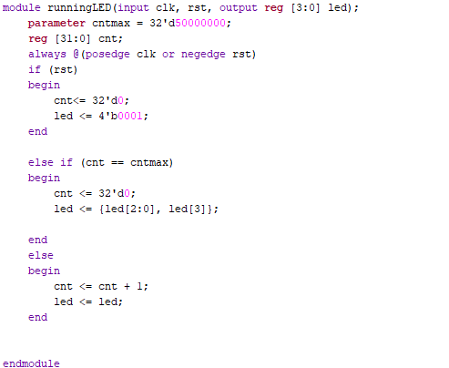
Task 2 was a running LED with three states, 4-LEDs Slow, 16-LEDs slow,
and 4-LEDs fast. The only difference between the 4-LEDs fast and slow
is changing the cntmax parameter from 1s to 0.5s by dividing it by 2.
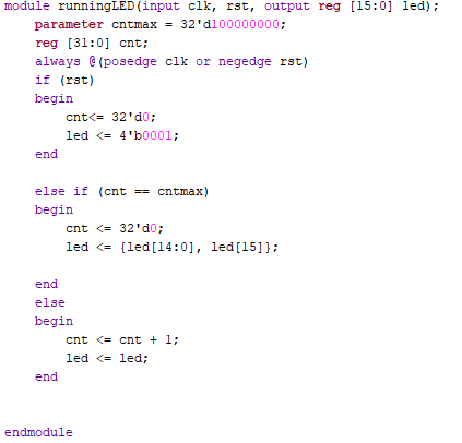
For the 16-LEDs all I had to change was number of LEDs in use from
[3:0] to [15:0] as well as changing the shifting logic to shift the
[15] bit to the end instead of the [3] bit. I am not going to write
more on these since they are very straight forward and almost
identical. The longest part of these three sections was waiting for the
code to upload to the board, in hindsight I could've let all three play
in series so that I only had to upload once.
Figure 7. 4
Runnin LEDS Slow Module, TB, and Demo on Basys 3.
Figure 9. 4-Running LEDs Fast Module, TB, Basys 3 Demo.
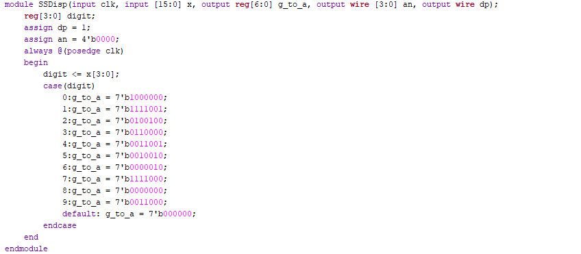
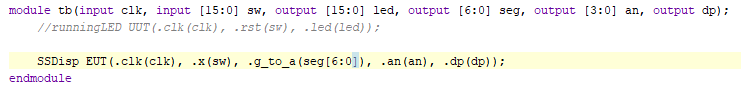
Task 5 The
final task was to count using the switches on the basys 3 board and
display the count in decimal on the Seven-Segment Display. This was
done using a case statment to decode the binary value into the
corresponding segment to form a digit. Where bits were high the segment
would be off while low bits turn that segment on. The An variable is
used to select which SSD the value is displayed on in this case, all 4.
Figure 10. SSD Module, TB, and Basys 3 Counting Demo.