I started by writing the code for examples 2.1 - 2.3 in gVIM which can be seen below in Figure 1.
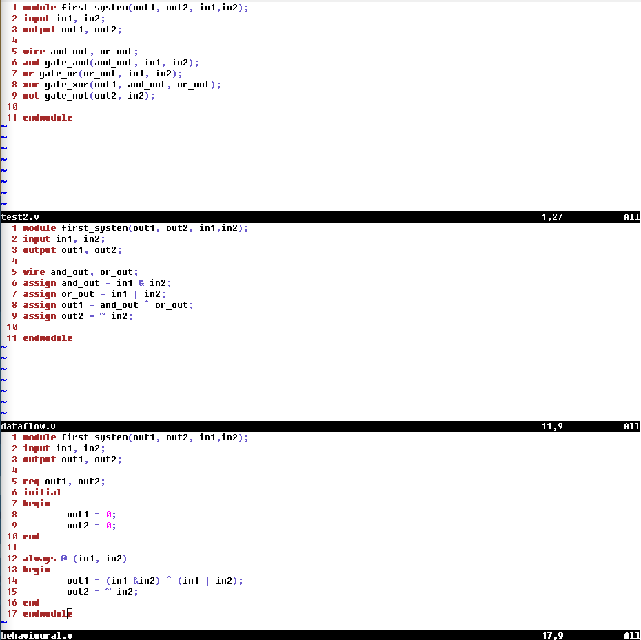
Figure 1. HDL code for the same circuit in three different programming styles.
These code blocks all have the same functionality but are written in different styles. The first script uses structural modeling to model the gates and then extract the circuit behaviour, the second code block is dataflow modeling and is the most familiar to how I typically program in Python or C++. The behavioural modeling seems useful if you care about the intermediary logic but the code seems slightly more complex from this first trial.
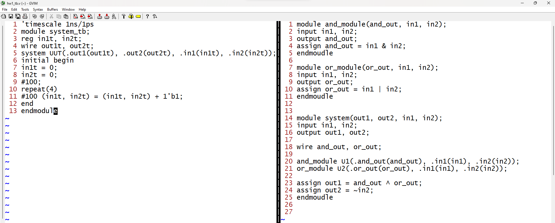
The code was then simulated using the testbench code seen in Figure 2.
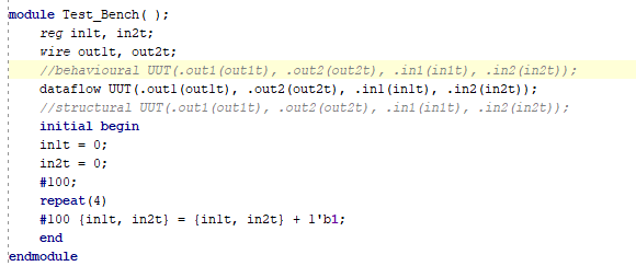
Figure 2. Test benches for all three simulations.
Since these scripts were almost identical the same test bench can be used by simply chaning the name of the UUT.
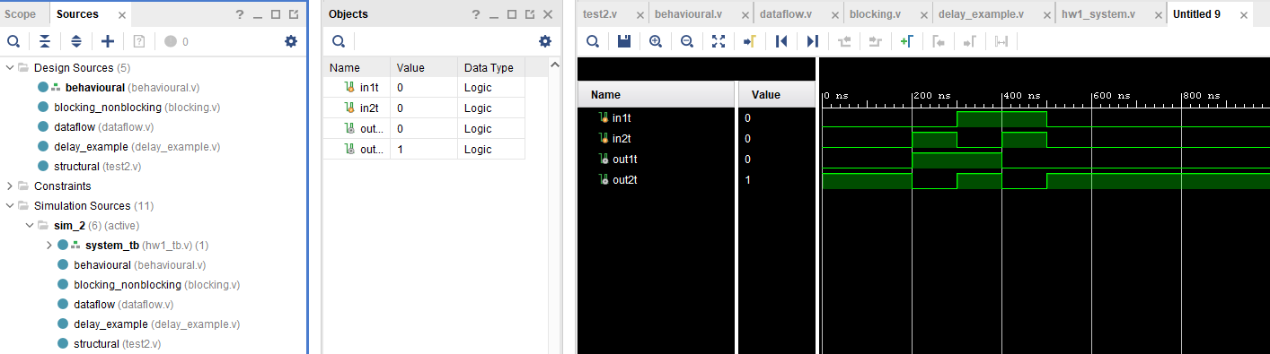
I ran all the simulations and to no surprise they were all the same so for concision I am only putting a single photo for the simulation results in Figure 3.
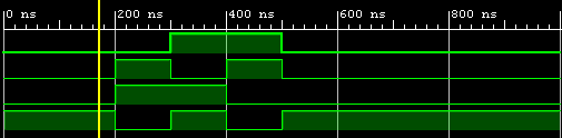
Figure 3. Simulation results for the scripts written in 2.1-2.3
To demonstrate blocking and non-blocking the following HDL code was written
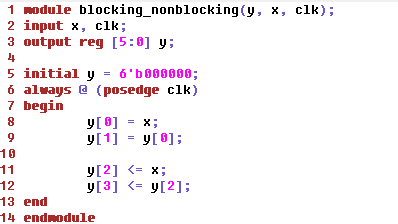
Figure 4. Blocking and Non-Blocking HDL example script.
The testbench was then setup in vivado, almost the same as the prior examples but this time the clock is switched every 10ns.
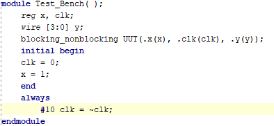
Figure 5. Testbench for Blocking and Non-Blocking example.
The testbench wasa then run and yielded the following output.
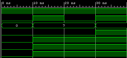
Figure 6. Blocking Non-Blocking simulation.
You can see that the non-blocked value (Y[3]) didn't change until the second rising edge since on the first rising edge y[2] was still 0 when y[3] checked for the update.