Embedded Systems
Spring 2024
HW 5 Sequential Circuit
Name: Mason
Brady
Email:
mrbrady1@fortlewis.edu
HW 5
Introduction:
This homework is an introduction to Combinational Logic Blocks
Materials:
gvim, vivado
1) Find the logic equation for q1(n+1) and y and draw the seuential circuit
So
using the logic table I found the logic expressions. The q2(n+1) was
slightly harder than the y since it needed the reduction but y could
only occur at one spot in the logic table the small work required can
be seen in Figure 1. The diagram for this got a little messy and there
are three wires I accidentally shorted when I meant to and them.
They're crossed out reight before going into the and gate.
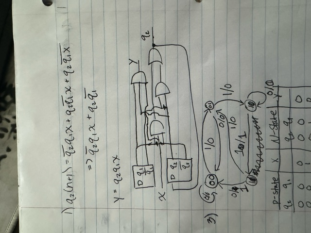
Figure 1. Logic derivation for q2 and y and circuit diagram.
2) Given and Behaviaoural Simulation of Section 3
For
this task I just wrote the sequence detector we were given and then
wrote the behavioural version. The behavioural version is easy because
you just need to map out each output for each input and then use a
case. For the testbench I just created two wires for each module so I
could test both simultaneously, one uses a two bit wire while the other
uses two one bit wires, then I wrote the short given form loop to test.
The code can be seen in Figure 2.
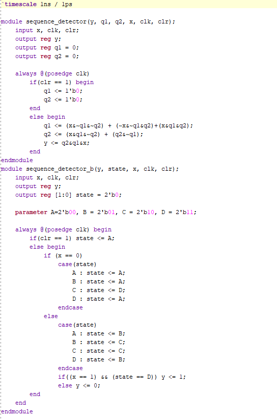
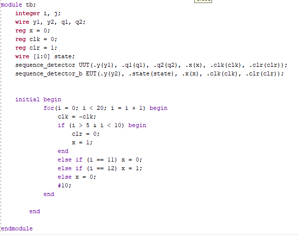
Figure 2. Test bench and module for sequence detector
The
simulation output was as expected when compared to the provided logic
table. Both Y1 and Y2 went to High once the given sequence was input.
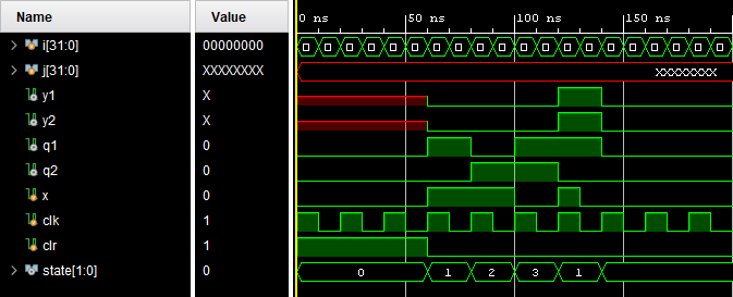
Figure 3. Simulation for Sequence Dectectors.
3) Change the sequence to 1011
The
first thing I had to do here was figure out the propper logic table and
expressions. Since the given code was 1101 you simply set the
transition to move to the next node to the corresponding bit value in
the sequence. One important note is that since the first two bits are
11 after the first two ones the user can keep inputing a 1 and reach
the correct sequence so even though it doesn't further the sequence the
second and zero node can loop on 1 and 0 respectively, the other two
nodes return to node zero when they are incorrect. From the logic table
I then derived the logic equations and drew another very messy diagram.

Figure 4. On Paper Work for Sequence Detector 1011.
From
this, implementation is very easy and I used the exact same code as
before just changing out the logic expressions to be the same. I then
ran the simulation and recieved the expected result. When the
corresponding code is input in the beginning Y1 goes to high. When
incorrect codes are input nothing happens.
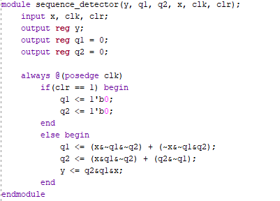
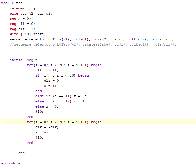
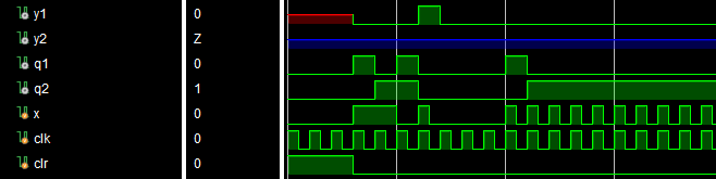
Figure 5. HDL and Simulation for Modified Sequence Detector.
4) Build 4 Shift Registers and Simulate
The
4 different shift registers are serial in serial out, parallel in
parallel out, and either combination of the two. They are farely simple
to program in HDL with the most complicated being the PISO but not by
much. Basically these just store values and move them out so they are
quite straightforward. To make it more fun I tried to simulate them all
at once which added some difficulty to load everything in properly and
make sure that the timing works for all of them to be readable. PO 1 is
PIPO PO2 is SIPO which is why the PO2 is only correct around 40ns while
the PO is correct the entire time.
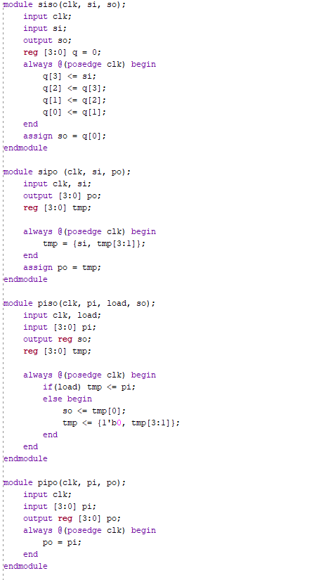
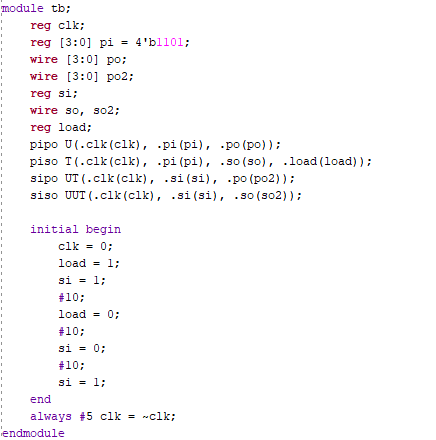
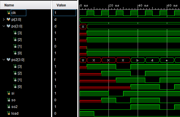
Figure 6. HDL, TB, and Simulation Results for 4 Shift Registers.
5) Build Counter Module and Simulate
For
the counter it was quite straightforward, I ended up writing both an
Nbit and a two bit because I thought the nbit was bugged for some
reason (I had my output wire q as a single bit) but then I fixed it
when I made the two bit counter but the simulation test bench should
work for both which is why theres some extra shenanigans in the
testbench. The Simulation is exactly as expected, counts to 3 then
resets to 0 and flips y.
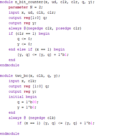
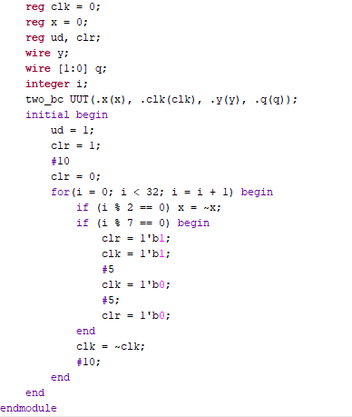
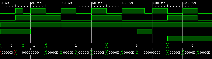
Figure 6. Two Bit Counter Module, TB, and Simulation.
6) Find the Logic Equations and Simulate
The
first thing I did for this was create a state table for the given
circuit. From this I could get qa. For qb and z their states are
immediatley obvious (so is qa honestly).
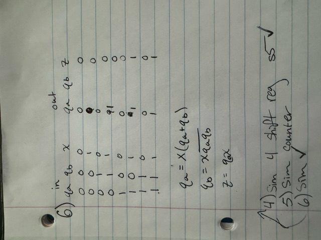
Figure 7. Logic Table and Extrapolated Logic Statements.
From
this I modified the sequence detector code for the above logic
statements and slightly modified the test bench to reach all of the
required cases. Its curious to note since I was using nonblocking
assingment y gets updated a full clock cycle late. I also probably
shoudl've slowed down x to two clock cycles but it worked fine to demo.
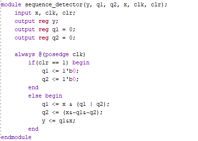
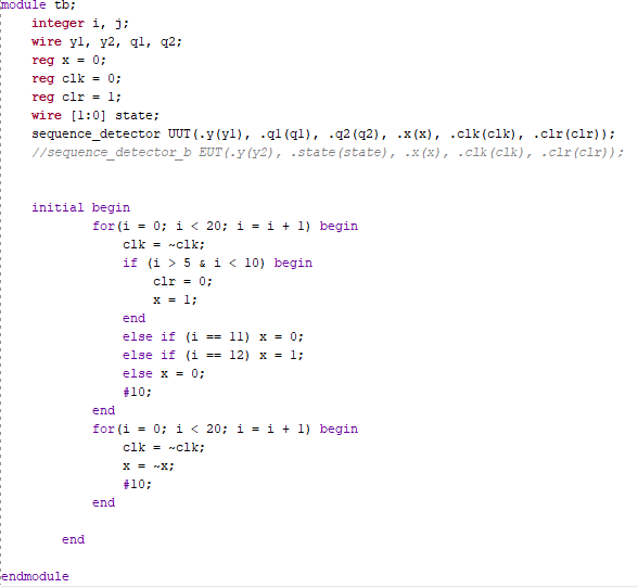
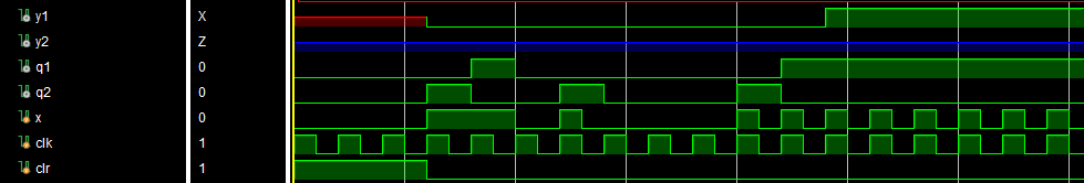
Figure 8. Modified Sequence Detector 2.
Discussion:
This
weeks work was pretty fun didn't mind this one at all.