Methods: The background light was measured with the LED off and the ambient light was 337, the LED was then turned on to read 641 so I set my setpoint to 500.
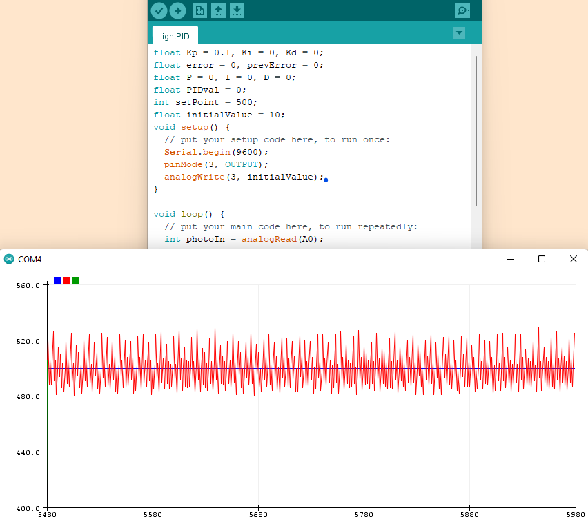
Figure 1. Light oscilating around the setpoint, 500.
A python script was then written to interface with the serial port that the arduino was reading into. Matplotlib was used to make a real time plot over the course of 2 seconds and can be seen below in Figure 3. Spikes can be seen where the button was pressed turning on the white led followed by a fall when the button was released. I think the noise reducess while the white light is on because the white light provides a more stable reading over the red LED.
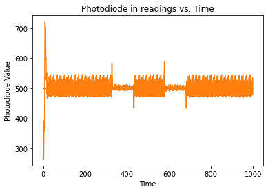
Figure 2. Matplotlib plot of serial read in from photodiode.
Finally, the equilibrium point was increased by wiring the button to digital 4 and writing a brief script to check if the button was pressed before increasing the setpoint. The python graph of this can be seen below in Figure 3. The blue line is the setpoint and the orange line is the read in value of the photodiode.
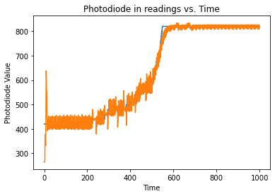
Figure 3.