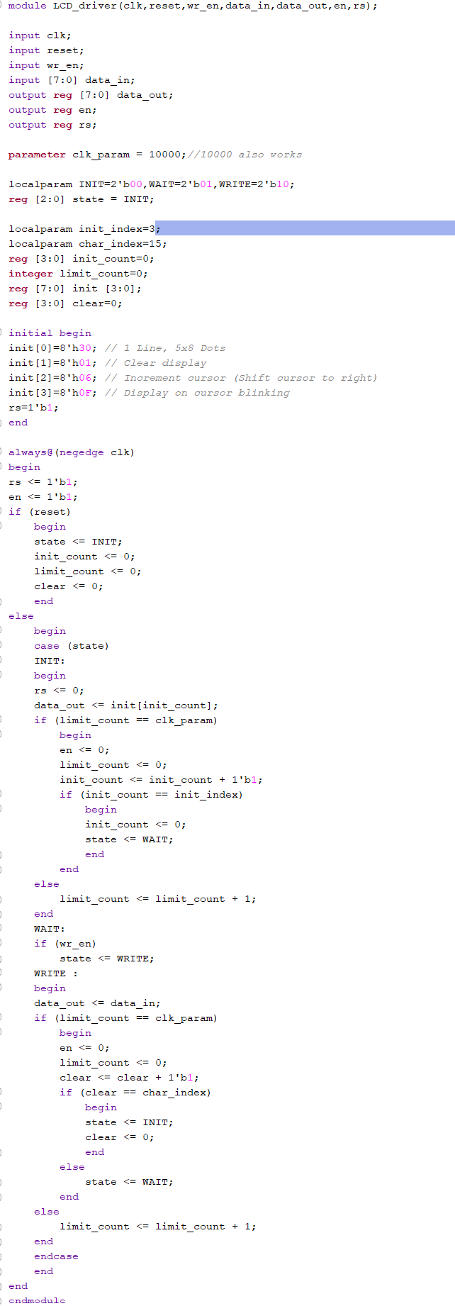
This assignment was an introduction to using a LCD screen with the FPGA board. All LCD modules created
in each task use the LCD driver module below. Figure 1: LCD driver module.
Task 1:
Task one was implement the
LCD program from the textbook, displaying different words depending on
the switch enabled on the FPGA board.
Figure 2: Textbook LCD code.
Figure 3: Textbook LCD demonstration.
Task 2:
Task two was to
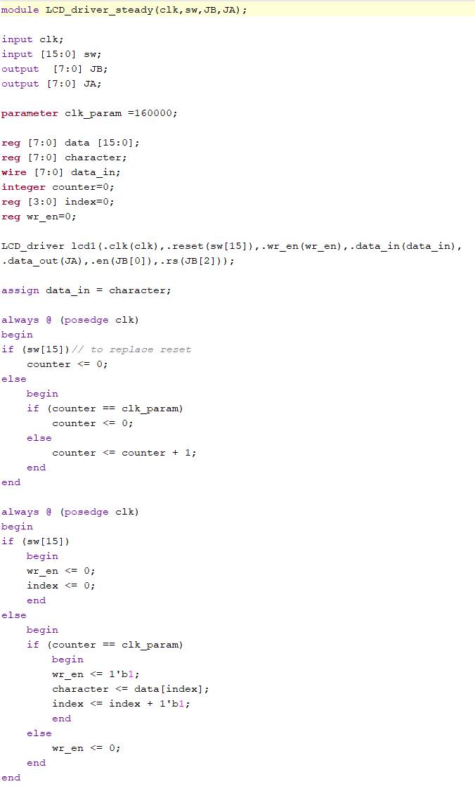
modify the program from task one to display steady state words rather
than having the LCD spell out each word. This was done simply by
changing theclk_param value to be lower, making the transitions too fast to be seen.
Figure 4: Steady state LCD code.
Figure 5: Steady state LCD demonstration.
Task 3:
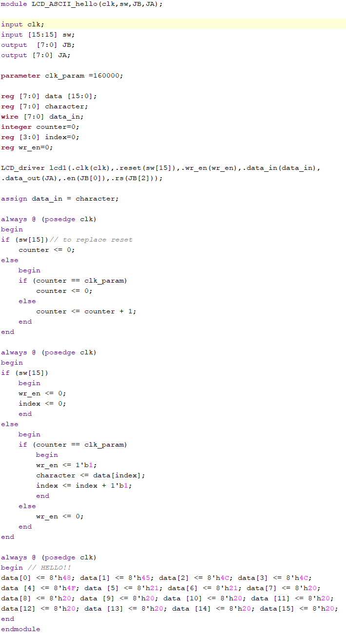
Task three was to
modify the program from task two to display only "Hello!!", but coded
using ASCII hex values rather than typing each letter out in the
Verilog code. Figure 6: Hello!! ASCII code.
Figure 7: Hello!! ASCII demonstration.
Discussion:
This
assignment was good introduction to using a LCD module with the FPGA
board. I had trouble with the pin definitions in the constraint file
and implementing the pinouts correctly. The problem was that the
constraint file defined JA[4:7] as physical ports JA 7-10. After
getting help from Dr. Li and Noah, they identified the issue and the
rest of the assignment didn't cause any issues.