This assignment was more
experience using the VGA port and with timing. All VGA modules created
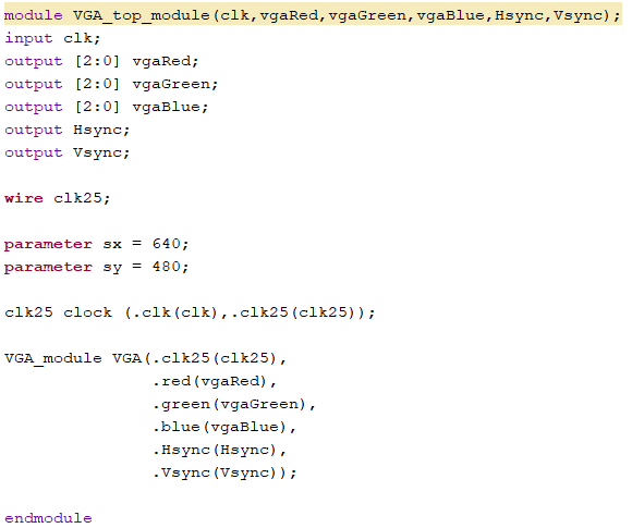
in each task use the VGA top module below. Figure 1: VGA top module.
Task 1:
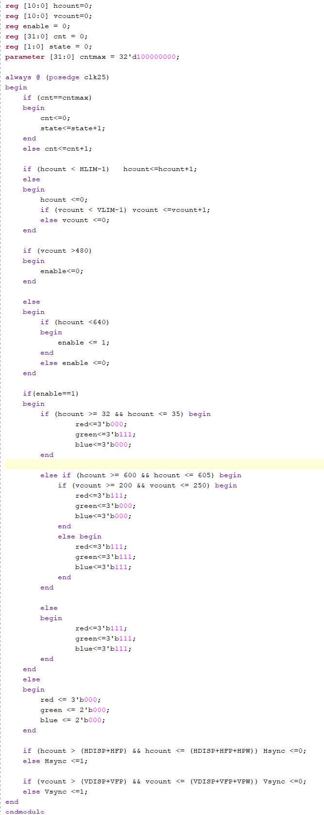
Task one was to create a program that draws a green line on the screen between x = 32 to 35 and top to bottom.
Figure 2: Green line code.
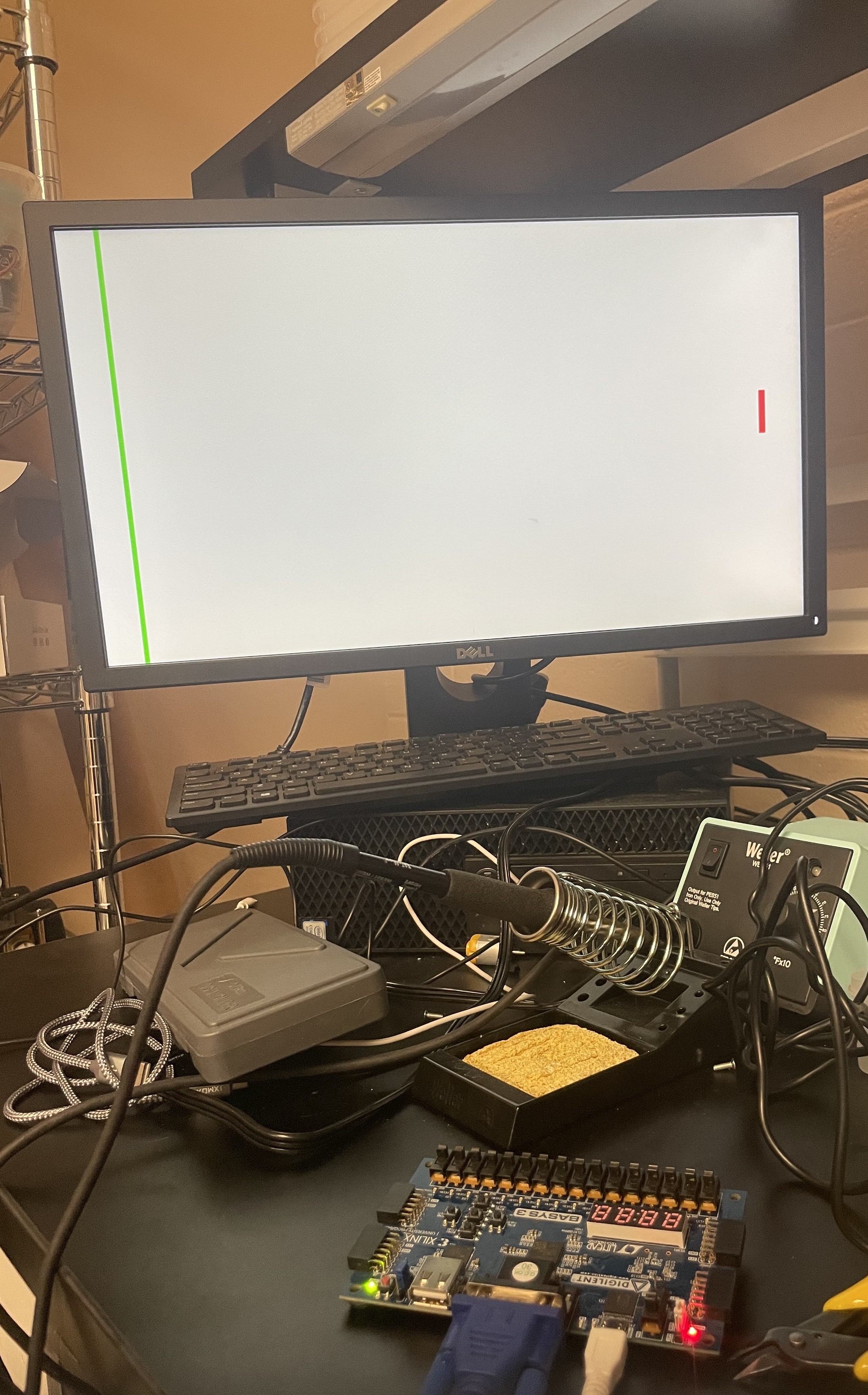
Figure 3: Green line demonstration.
Task 2:
Task two was to
modify the program from task one to add a red line on the screen between x = 600-605 and y = 200-250. Figure 4: Green and red line code. Figure 5: Green and red line demonstration.
Task 3:
Task three was to
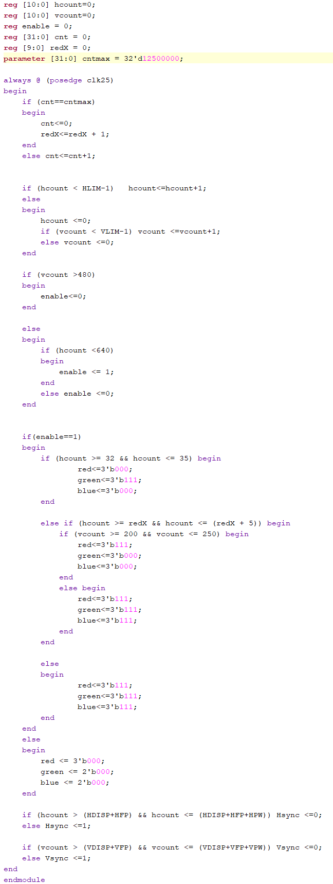
modify the program from task two to make the red line crawl across the
screen, left to right, behind the green line. The red line should move
at a speed of one pixel per half second or 2pixel/s. Figure 6: Red line crawl code.
Figure 7: Red line crawl demonstration.
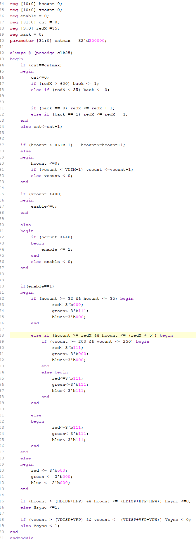
Task 4:
Task four was to
modify the program from task three to make the red line bounce across the
screen from the green line to x = 600. The red line should move
at a speed of one pixel per 0.01s or 100pixel/s. Figure 8: Red line bounce code.
Figure 9: Red line bounce demonstration.
Discussion:
This
assignment was good experience using the FPGA board and VGA output.
After homework six, I still didn't feel very confident using the VGA
port. However after this lab I feel much more comfortable using the VGA
port. I did run into an issue on the last problem where the red line
would get stuck at either end, but other than that my programs did not
require much debugging if any.