Lab5: Three Bit Adder
Name: Lucien Verrone Email:
ljverrone@fortlewis.edu
Introduction:
This assignment uses
switches, LEDs, and the seven segment display to implement a three bit
adder with two's compliment and a function toggle (+ --> -).
Task 1:
Task one was to implement a three bit adder on the FPGA board.
The inputs are seven switches, two sets of three switches to input two
three bit binary numbers and one switch to toggle between addition and
subtraction. The outputs are four LEDs that represent a four bit binary
output in two's complement format.
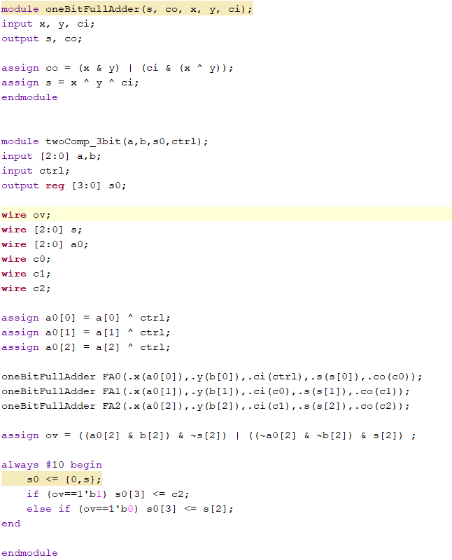
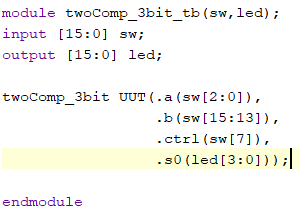
Figure 1: Three bit adder with LED display code.
Figure 2: Three bit adder with LED display demonstration.
Task 2:
Task two was to
modify the program from task one to instead display the result from the
three bit adder as a signed decimal on the seven segment display. This
was done by using a clock to switch between two states, one that
updates the second display to a negative sign if the sign bit is high,
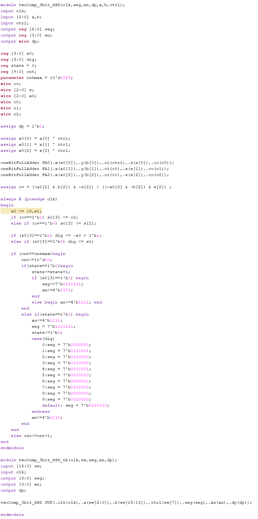
and one that outputs the absoulte value of the result. Figure 2: Three bit adder with SSD code.