This assignment used a
traffic light scenario to teach about combinational logic blocks,
k-maps, truth tables, and boolean algebra. The lab is short but
challenging, focusing on creating one, efficient program that is then
modified/adapted to later tasks.
Task 1:
Task one was to implement a the traffic system described above in both a simulation and on the FPGA board using k-maps and a truth table to find boolean logic expressions for each light.
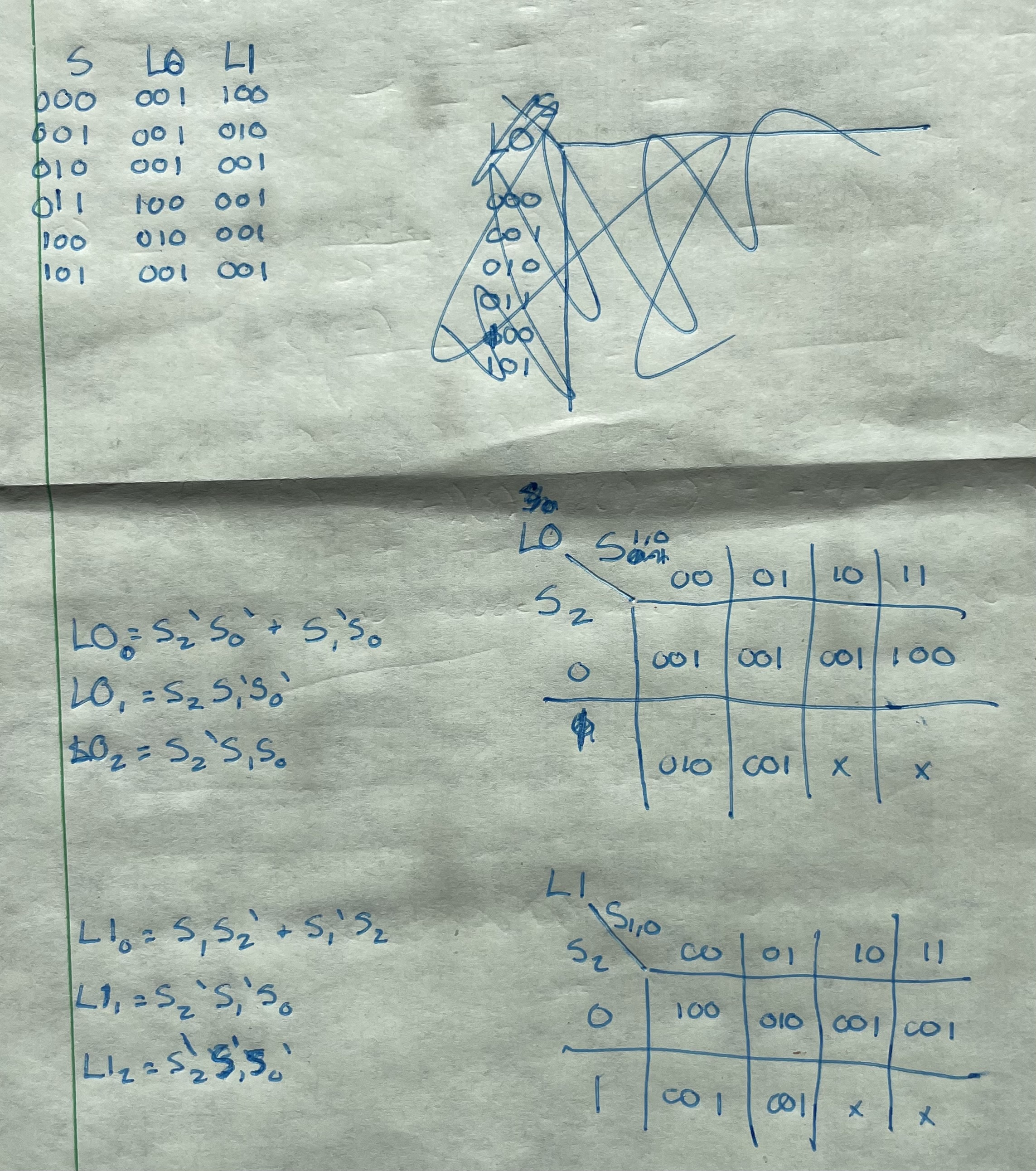
Figure 1: K-maps, truth table, and boolean logic for the stoplight. S
is the state while L0 and L1 are lights zero and one, all are three bit
binary numbers.
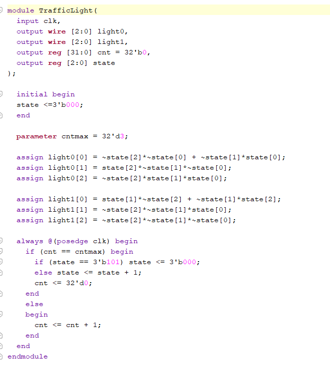
Figure 2: Traffic light code.
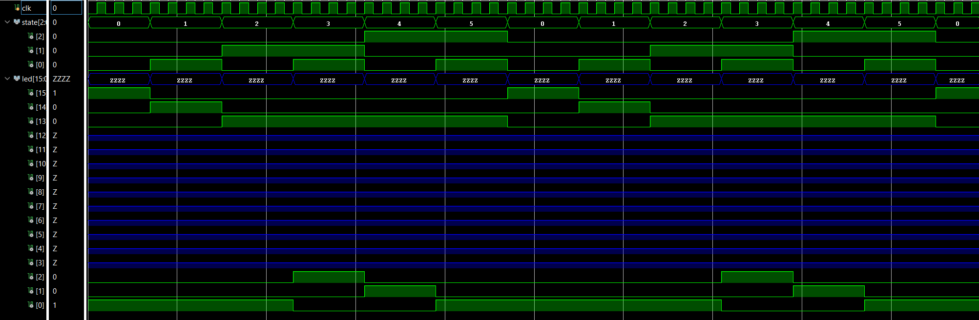
Figure 3: Traffic light simulation.
Figure 4: Traffic light demonstration.
Task 2:
Task two was to
recreate the traffic light program above, but with a switch that will
toggle "rush hour mode" which doubles the length of one road's green
light as to allow more traffic to busier roads at busier times. Figure 1: K-maps, truth
table, and boolean logic for the stoplight with an added green light state for light one. S is the state while L0 and
L1 are lights zero and one, all are three bit binary numbers.
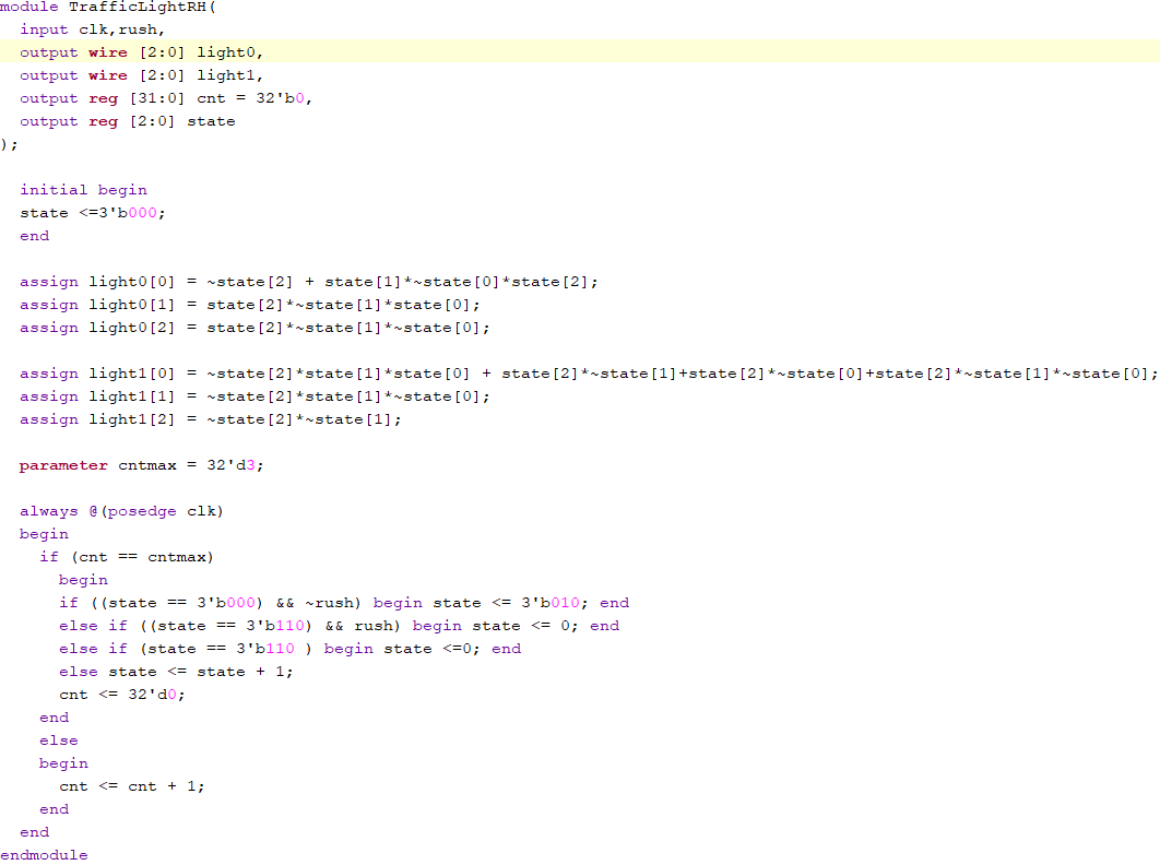
To account for the rush hour mode, an extra green light state was added
for light one. Then, during the loop, the program checks for the rush
hour mode switch and skips the extra segment if disabled.
Figure 2: Traffic light with rush hour mode code.
Figure 3: Traffic light with rush hour mode demonstration.
Discussion:
This assignment was a
challenged my logic and Verilog skills greatly. I was confused and
frustrated at parts, but learned a lot about debugging. Using
simulations, I was able to pinpoint errors in my boolean logic
expressions which, after I got the hang of it, became an integral tool
for the rest of the lab. While the rush hour mode served as more
practice for my boolean algebra and debugging, the approach felt very
natural and clear to me which sereved as a well needed confidence boost.