CE 433 Embedded Devices
HW5: Sequential Circuit
Name: Lucien Verrone
Email:
ljverrone@fortlewis.edu
Introduction:
This assignment was more
experience with states, along with creating state diagrams and
implementing them in Vivado. In all, this assignment required, sequence
detectors, shift registers, counter modules, and logic equations
synthesis.
Task 1:
Task one was to find the logic equations for q1(n+1) and y given a circuit and represent these equations as seperate circuits.
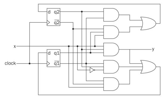
Figure 1: Given circuit.
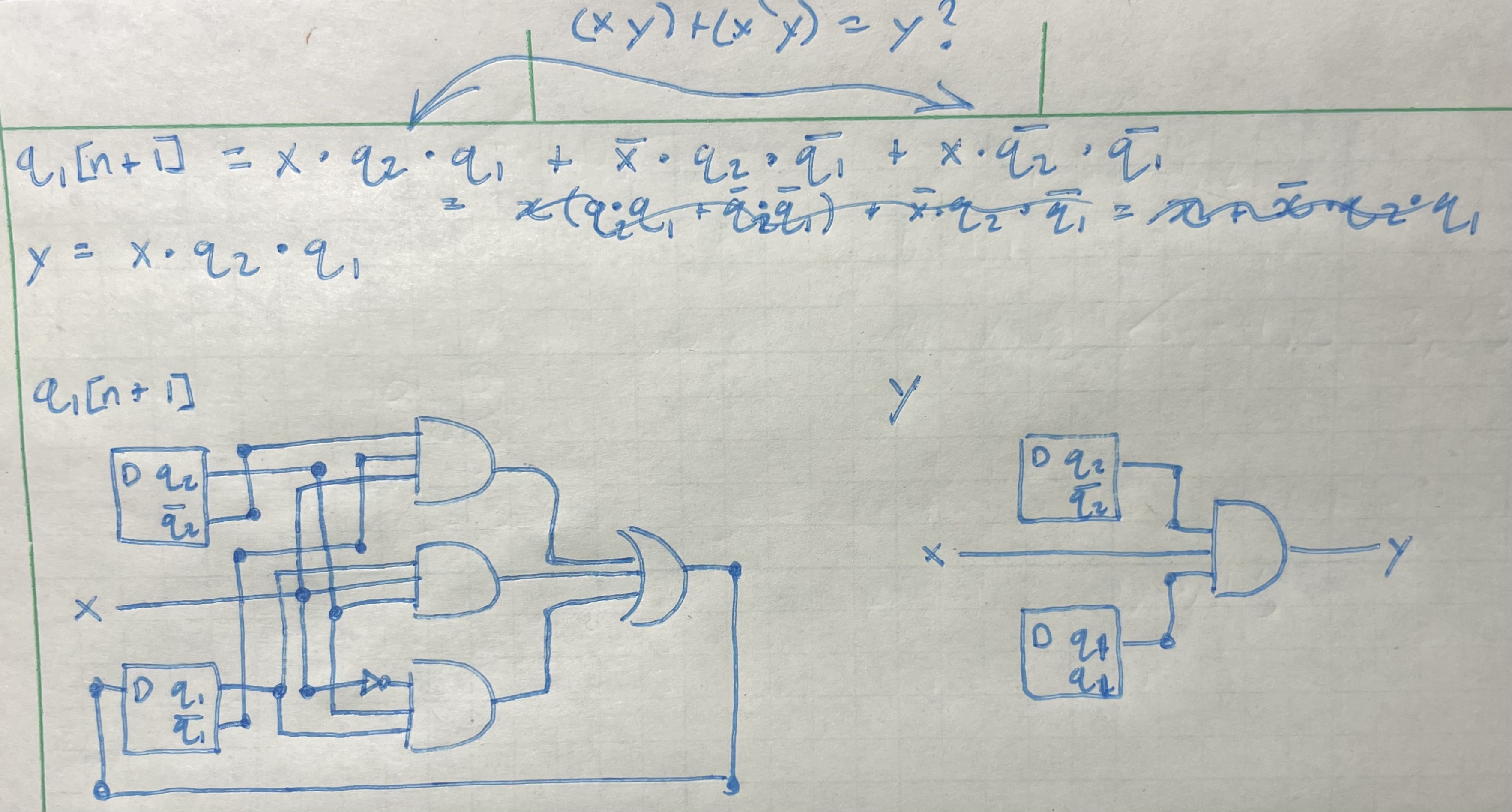
Figure 2: Logic equations and output circuits from given circuit.
Task 2:
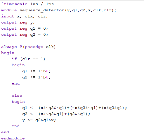
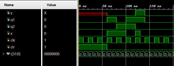
Task two was to implement a sequence detector using two methods, logic equations and a case statement using a state varaible.
Figure 3: Sequence detector code using logic equations and simulation.
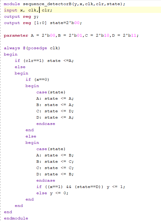
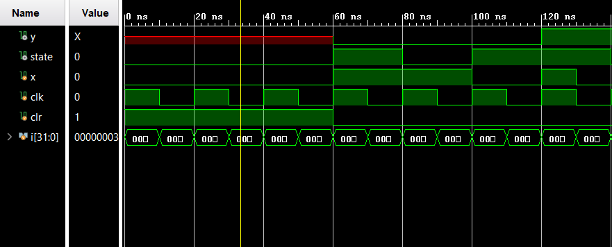
Figure 4: Sequence detector code using case statements and simulation.
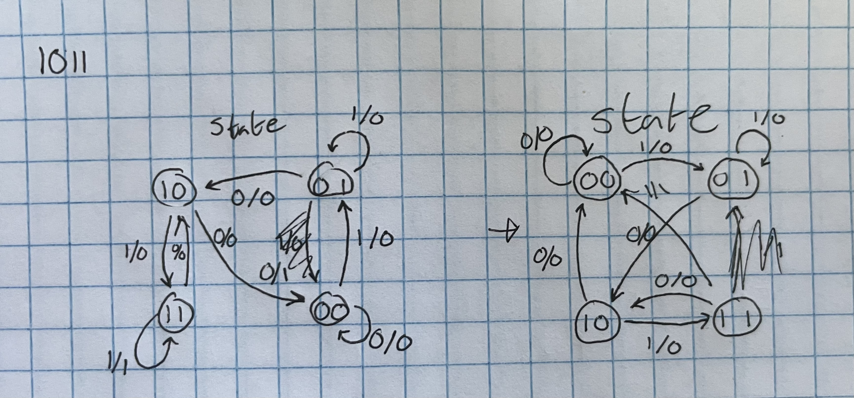
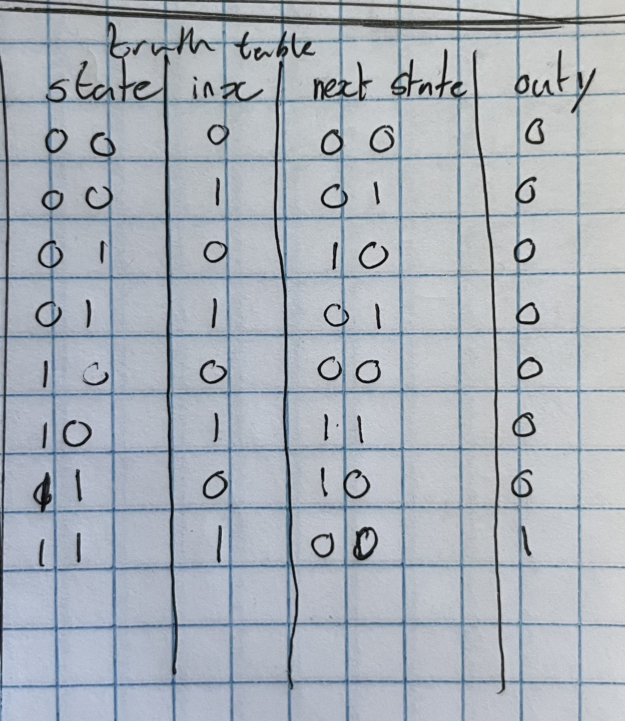
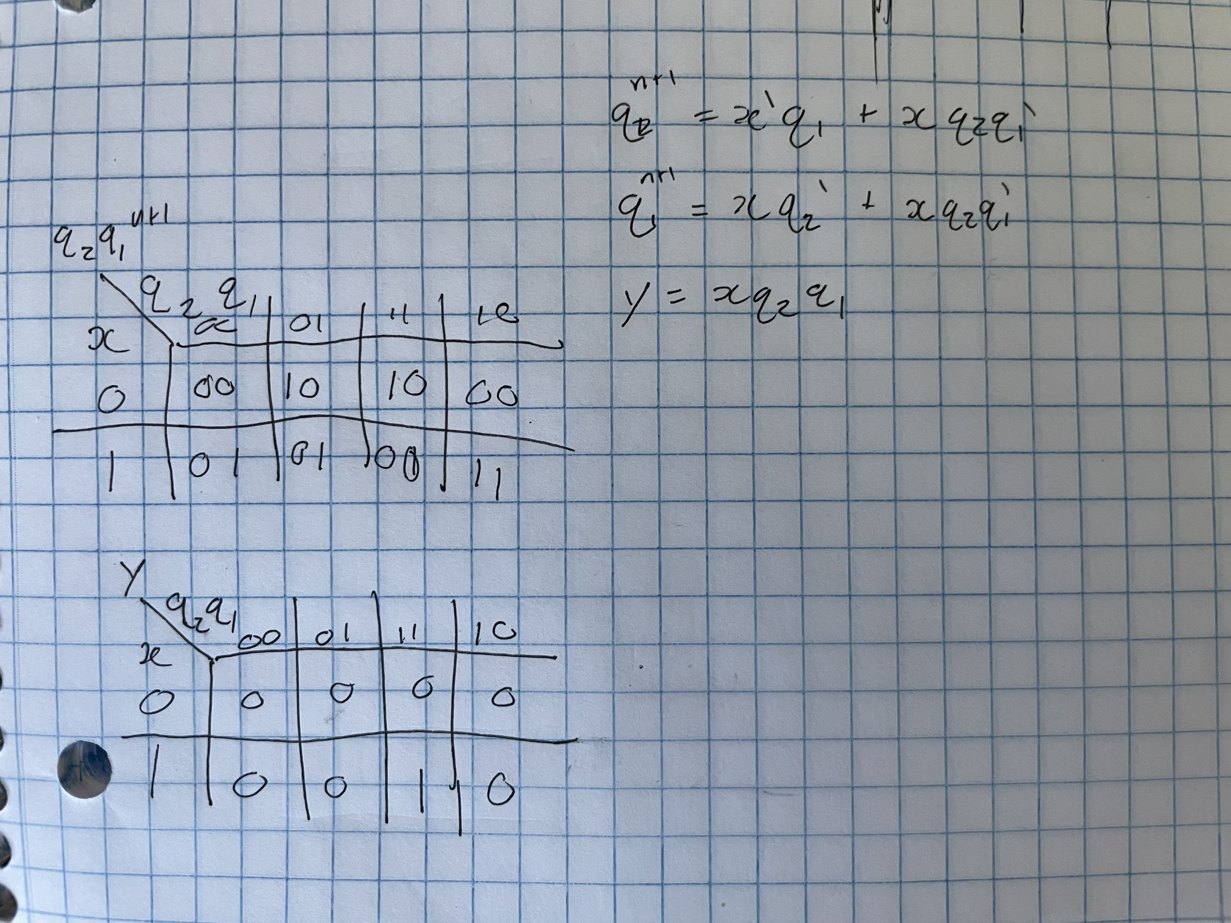
Task 3:
Task three was to modify
the module from task two to detect the sequence 1011. This was done by
drawing a state diagram, creating a truth table, and finding the logic
equations. The module was then simulated to confirm validity.
Figure 5: 1011 sequence detector state diagram, truth table, and logic equations.
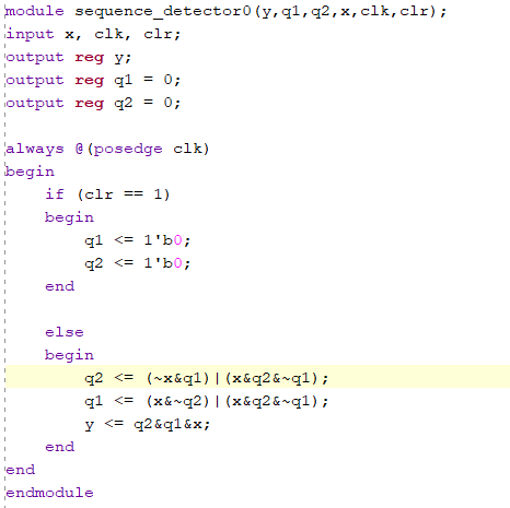
Figure 6: 1011 sequence detector code and simulation.
Task 4:
Task four was to simulate
four types of shift registeres: serial in serial out (SISO), serial in
parallel out (SIPO), parallel in serial out (PISO), and parallel in
parallel out (PIPO).
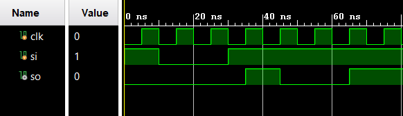
Figure 7: SISO simulation.
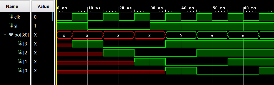
Figure 7: SIPO simulation.

Figure 9: PISO simulation.

Figure 10: PIPO simulation.
Task 5:
Task five was to build and simulate a counter module.
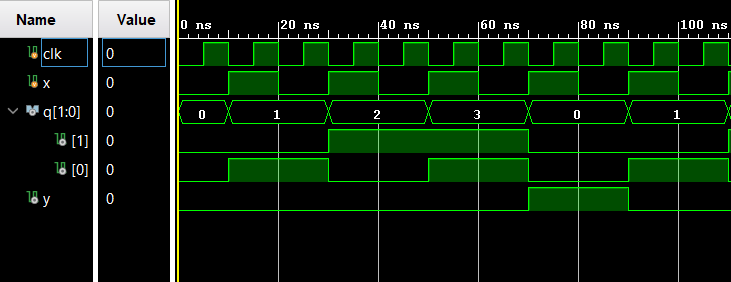
Figure 11: Counter simulaton results.
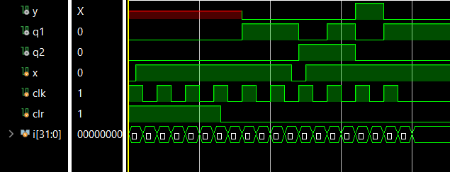
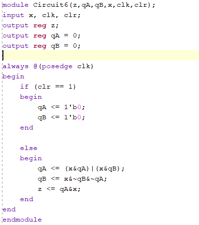
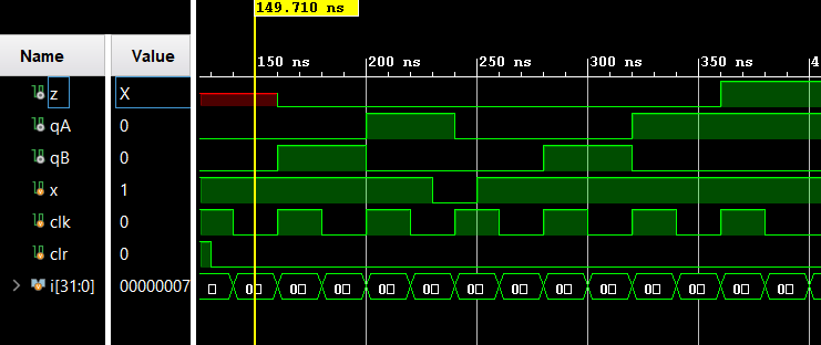
Task 6:
Task six was to find logic equations from a given circuit, implement these equations in verilog, and simulate.
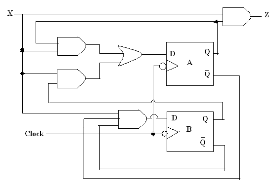
Figure 12: Given circuit.
Figure 13: Module code and simulation.
Discussion:
This assignment gave me more
practice using state diagrams, k-maps, and truth tables to implement
circuits in Vivado. Task three was challenging, but gave me valuable
experience converting to/from k-maps. I feel I have found a good
workflow from circuit to state diagram to k-maps to logic equations.