HW2: Data Types
Name: Lucien Verrone Email:
ljverrone@fortlewis.edu
Introduction:
This assignment was an
intro into FPGA programming and more experience simulating in Vivado.
Tasks included writing code in Vivado modeled off of the code shown
in class, creating test benches to simulate in Vivado, and pushing .bit
and .bin files for volatile and non-volatile storage.
Task 1:
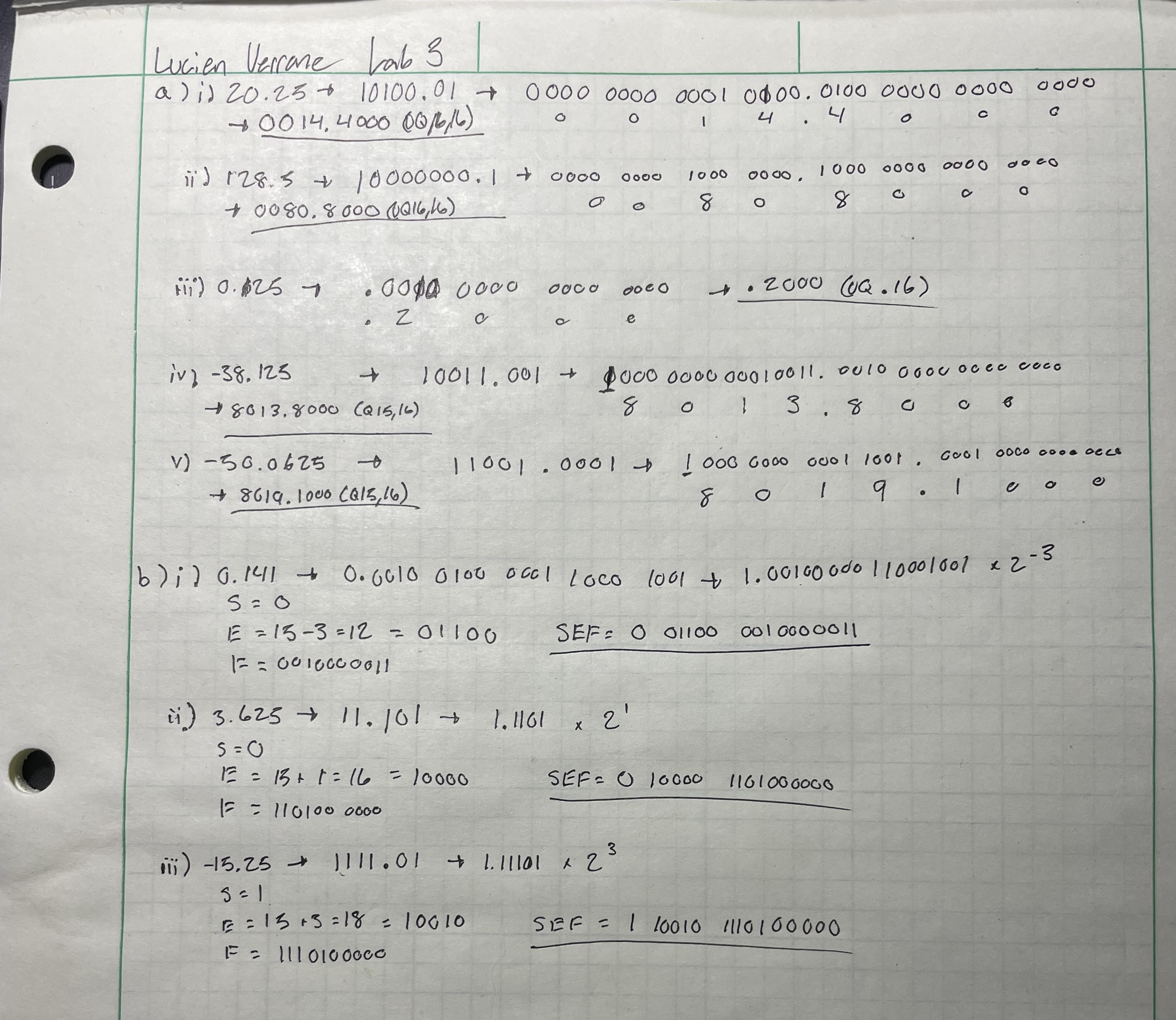
Task one was to convert decimal numbers into either Q format or half precision format.
Figure 1: Decimal to Q/half precision conversion.
Task 2:
Task two was to recreate
example code that was used to demonstrate datatypes. The module
recreated used a register to store a value and wires to read values
along with showing the manipulation of bits via assigning.
Figure 2: Simulation demonstrating trimming and assigning.
Task 3:
Task three was to recreate three FPGA modules and demonstrate
them: a home security module, a digital safe module, and a can
park module. The home security module took
input from switches representing sensors on doors and windows along
with a switch to turn it off and on. When a sensor is activated, the
module is triggered and the led switches.
Figure 3: Home security module demonstration.
The digital safe module took input from switches, requiring the correct input to switch from LED two to LED one.
Figure 4: Digital safe module demonstration.
The car park module took
input from switches representing car parking spaces in a car park. The
LEDs display the corresponding number of taken parking spots in
binary (ie. [1][0] = two spots taken, [1][1] = three spots taken).
Figure 5: Car park module demonstration.
Task 4:
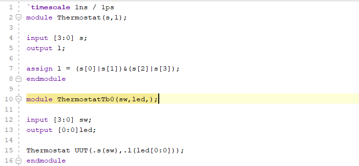
Task four was to design a
simple system similar to the examples given above. I came up with a
thermostat module that takes switches as temperature inputs from two
rooms on either side of a house.
If at least one room on both sides requires heating, the thermostat
will activate (the LED will trigger). If only one side of the house
needs heating, say if someone leaves a door open, the thermostat will
stay off and let the terperature even out.
Figure 6: Thermostat module code
Figure 7: Thermostat module demonstration.
Discussion:
This assignment was
challenging and required a lot more trouble shooting in Vivado than
past assignments. I ran into an issue a couple of times where the
hardware would blink in and out of connectivity, and had trouble with
the LED port because I declared it without identifying it as a vector.
Overall, I am more familiar with Vivado and have a better grasp on the
datatype nuance in Verilog.