CE 433 Embedded Devices
HW1: Vivado and Gvim Basics
Name: Lucien Verrone
Email:
ljverrone@fortlewis.edu
Introduction:
This assignment was a more detailed
intro into Gvim and Vivado, along with the workflow that goes between
both. Tasks included writing code in Gvim modeled off of the code shown
in class, and creating test benches to simulate in Vivado.
Task 1:
Task one was to recreate
examples 2.1, 2.2, and 2.3 from class. These examples also needed a
test bench and simulations in Vivado to verify the integrity of the
code. These examples are all modeling the same system.
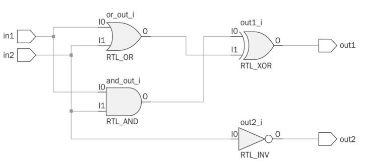
Figure 1: System that is being modeled by examples 2.1, 2.2, and 2.3.
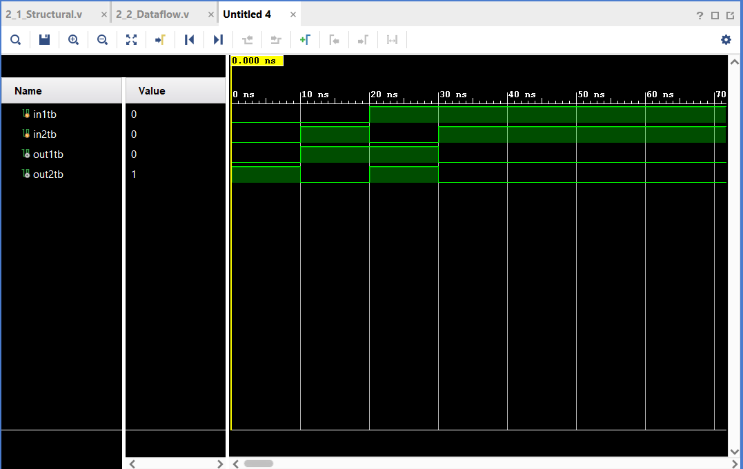
Example 2.1 models each gate individually, with the and and or
gates being coded first and the xor and not gates being coded with
those results. The test bench simply uses inputs and outputs one and
two to test the model in a simulation.
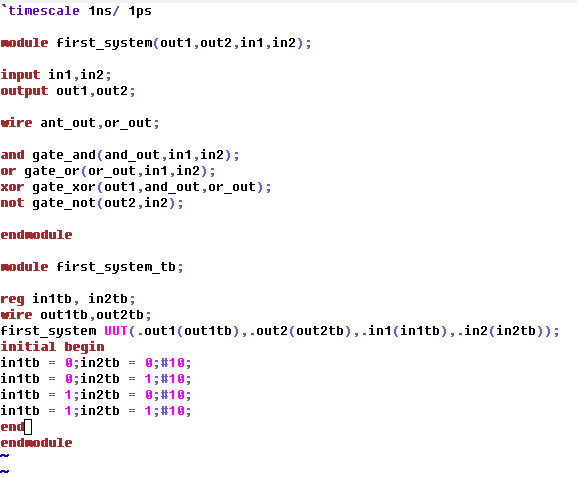
Figure 2: Example 2.1's Gvim code and Vivado simulation.
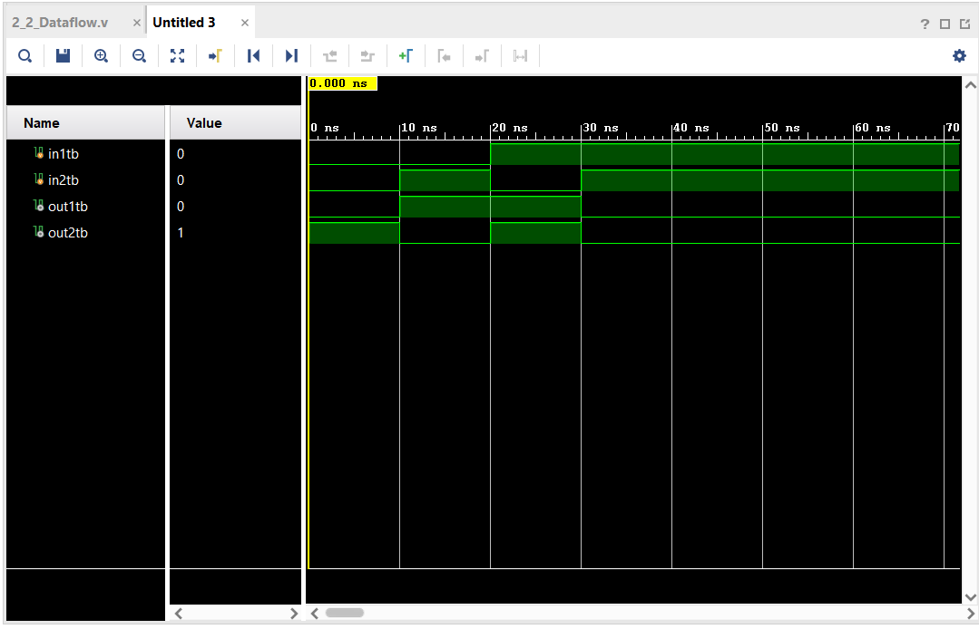
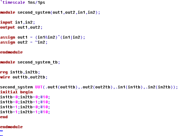
Example 2.2 models the
and and or gates with the xor and not gates. The test bench uses the
same inputs and outputs as example 2.1.
Figure 3: Example 2.2's Gvim code and Vivado simulation.
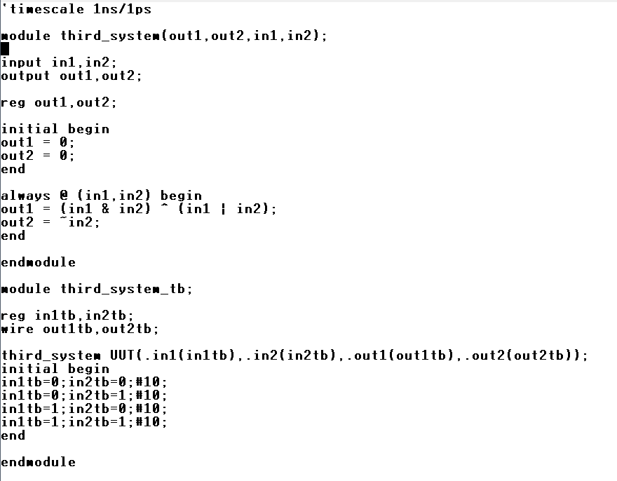
Example 2.3 models the
and and or gates with the xor and not gates only after the inputs are
changed. This was done by declaring the output assignments as always
processes dependant on inputs one and two. The inputs also have to be
declared and registers aThe test bench uses the
same inputs and outputs as example 2.1 and 2.2.
Figure 4: Example 2.3's Gvim code and Vivado simulation.
Task 2:
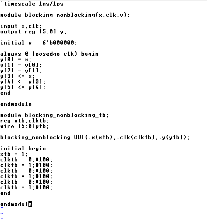
Task two was to
demonstrate the difference between blocking and non-blocking assignment
using example 2.4. This was done using an initial value and a clock
variable, with an always process activated by the rising edge of the
clock that controlls the blocking and non-blocking assignments. The
clock was assigned and reassigned, however I think there is a more
efficient way to create a clock like this I missed.
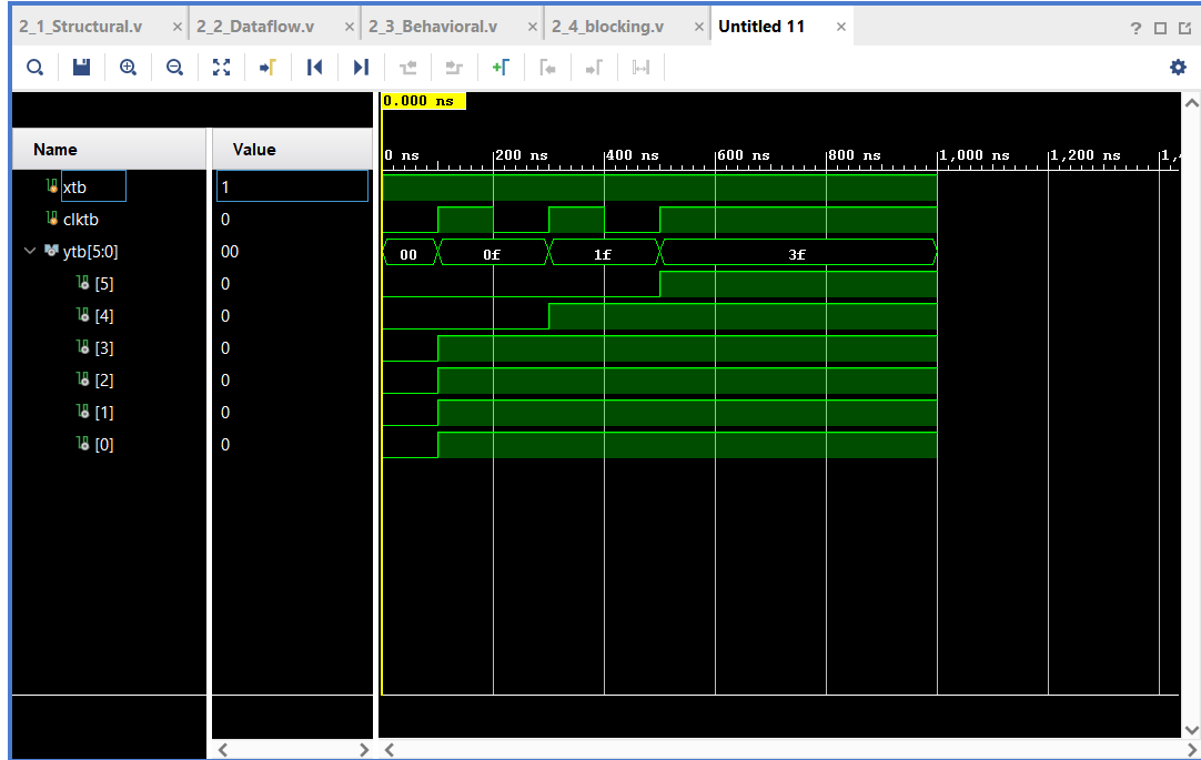
Figure 5: Example 2.4 and Vivado simulation. y[3:5] represent the nonblocking assignments.
Task 3:
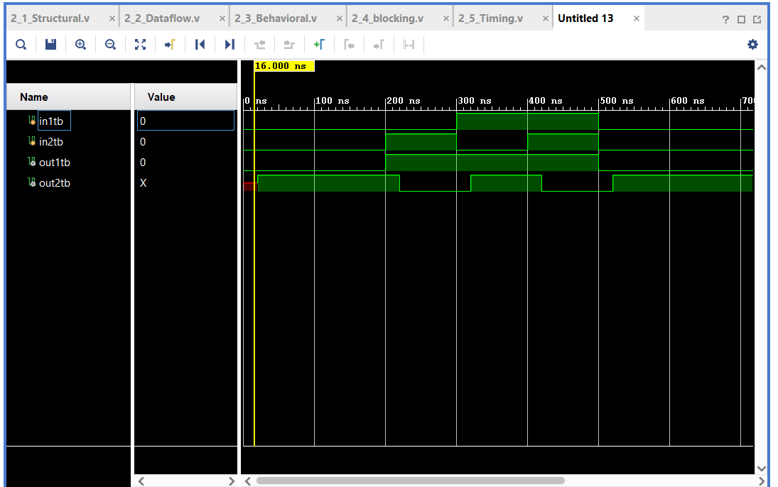
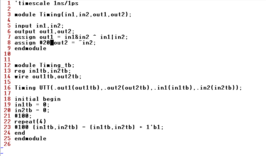
Task three was to recreate example 2.5 which demonstrates timing
delays. There is one 20ns delay in the model itself, and four 100ns
delays in the test bench.
Figure 6: Example 2.5 and Vivado simulation. The 20ns delay can be seen in the red portion of out2 in the simulation.
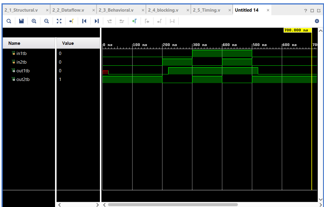
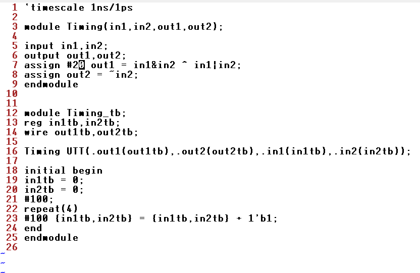
Task 4:
Task four was to move the 20ns delay a line up in example 2.5 and simulate the result.
Figure 7: Example 2.5 with 20ns delay moved and Vivado simulation. The 20ns delay can be seen to have moved to out1.
Task 5:
Task five was to hand draw an example timing diagram.
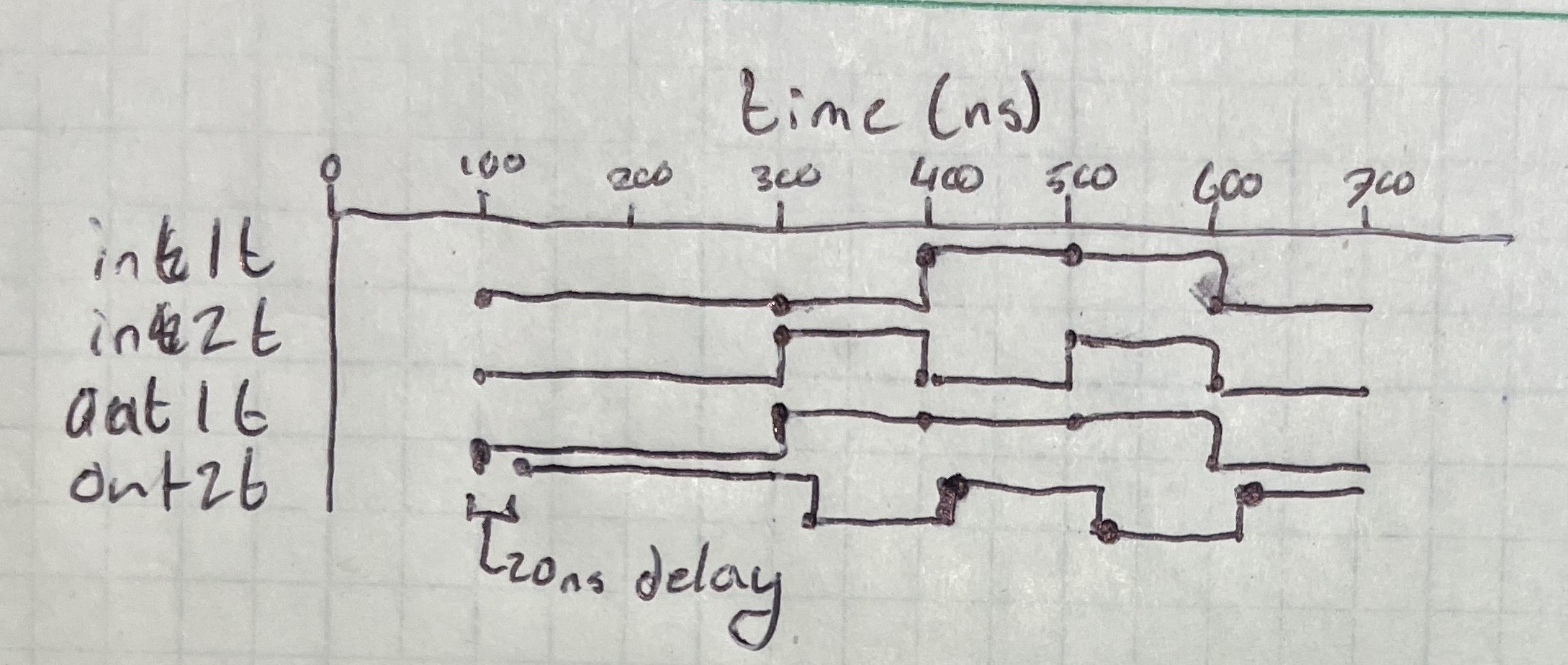
Figure 8: Hand drawn timing diagram.
Task 6:
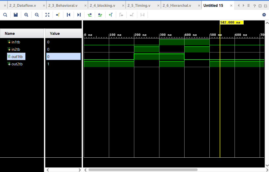
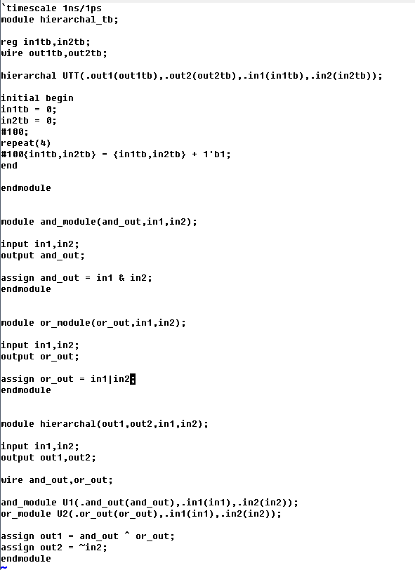
Task six was to recreate example 2.6. Example 2.6 demonstrates
hierarchial modules. Or and and gates are seperated into their own
seperate modules, which are then imported into the main module, which
is then imported into the test bench.
Figure 9: Example 2.6 and Vivado simulation.
Discussion:
This assignment
familiarized me further with Gvim and was my first time using Vivado. I
found myself becoming very comfortable with Gvim commands and Vivado
simulations didn't cause any issues. Beyond this, the different
approaches from each example taught me something new. Example 2.1 and
2.2 show the differences between using assign versus not, along with
combining functions. Example 2.3 taught me to use always processes, a
skill that is then used to create a loop to show the difference between
blocking and non-blocking in example 2.4. Example 2.5 introduced me to
the delay an repeat commands. Finally, example 2.6 showed
hierarchial structure for modules and the process of importing nested
modules. Overall, this assignment has made me feel better prepared to
handle coming labs and assignments using Gvim and Vivado.