Homework 8 - Embedded
Soft-Core
CE 433 Embedded Devices
2024 SpringTasks:
Repeat the work in Section 3 - 11 in this tutorial. Section 3 - 10: 10 points each, Section 11: 20 points.
Section 3. The workflow of SoC design using KCPSM6 and Basys 3.
In this task we are using eight input switches and turning on or off the corresponding leds.
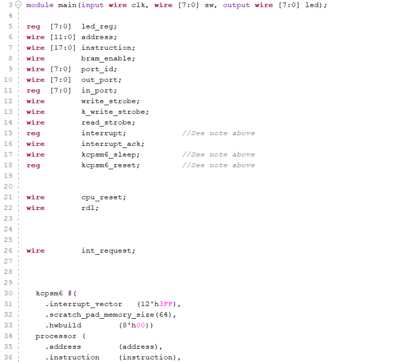
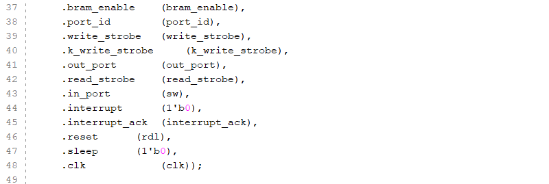
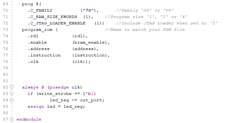
Figure 1: This is the top module.
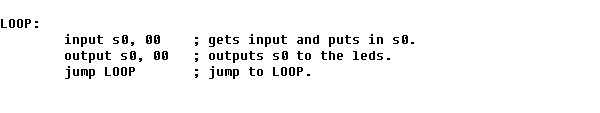
Figure 2: Task 3 program that outputs
the switches' corresponding LED.
Section 4. The Square Problem.
In this task the program is to take in eight switch inputs and calculating the the square of half of the inputs and adding them together and then display them on the leds.
Section 5. Assembly example:
adding a 0x13 to the LEDs.
In this task we are taking the input from the switches and then adding them to the hexadecimal 0x13 and displaying the output on the leds.
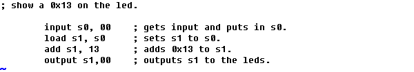
Figure 3: Task 5 program that
displays and adds 0x13 to the input switches.
Section 6. Assembly example: use
the MASK
In this task we are using a constant to make sure that the last two bits or the leds are always '1'.
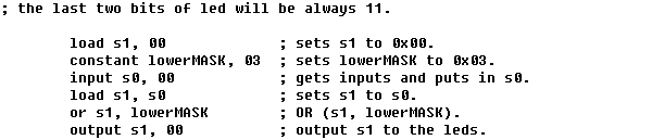
Figure 4: Task 6 program that always
outputs '1' on the two lest significant bits.
Section 7. Assembly example: shift
the sw input to the right by one bit.
In this task we are are taking the input from the switches and shifting them to the right by one bit and then output that to the leds.
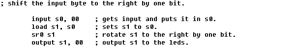
Figure 5:Task 7 program that takes
the input and shifts it to the right by one bit.
Section 8. Assembly example: use
jump, return, and load instructions.
In this task we are using jump, return, and load instructions, but taking in inputs from the switches and testing for the least significant bit, if false the outputs 0x06 to the leds, or if true then output 0x05 to the leds.
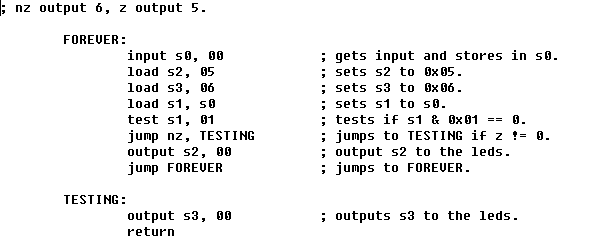
Figure 6:Task 8 program that outputs
0x06 when z == 0, and outputs 0x05 when x == 1.
Section 9. Assembly example:
practice with multiple subroutines.
In this task we are implementing the use of different subroutines this program sets s2 to 0x08 and s3 to 0x00. Then tests s2 against 0xff and then if Z == 0 then it jumps to 'NOTZ', if Z ==1 then it jumps to 'ISZ'.
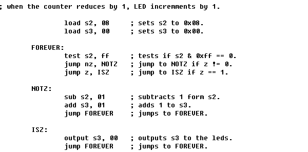
Figure 7: Task 9 program that uses
different subroutines to display 0x08, code that is written
should also increment / decrements the count or leds.
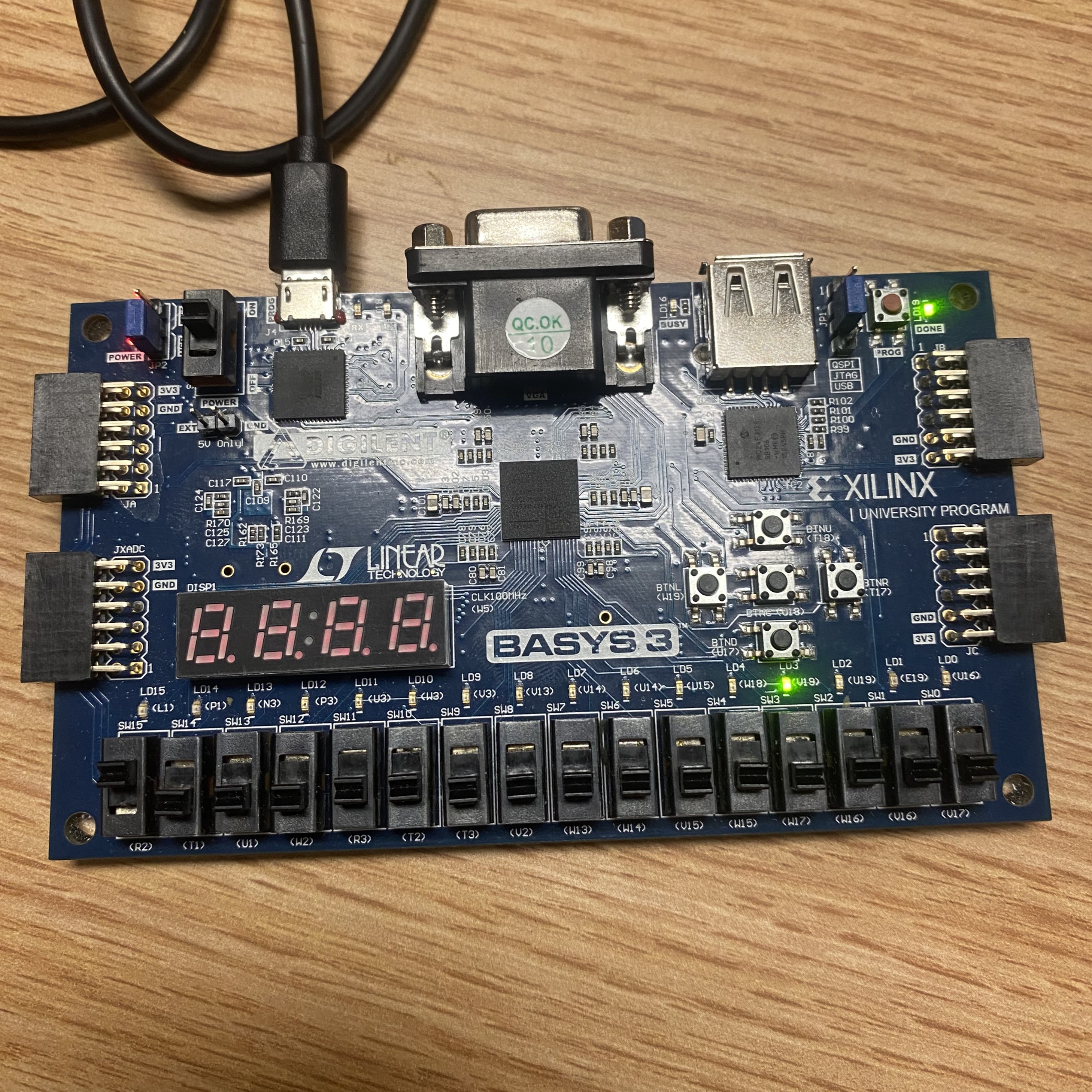
Figure 8:This is the result of the
task 9 program using different subroutines.
Section 10. Assembly example: use
the 'compare' instruction instead.
Within this task we are doing the same thing as section 9, but instead using the test operator, we use the compare operator.
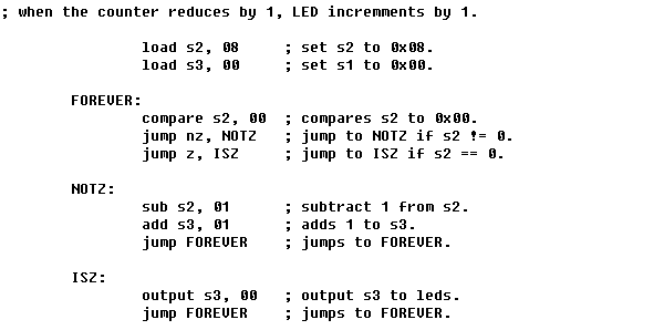
Figure 9: Task 10 program that does
the same thing as task 9, but using compare instead. THIS AS THE
SAME OUTCOME AS TASK 9.
Section11. Assembly programming
task - design an assembly code to show the number of switches
that are ON on the LEDs in the binary form. The results must
be able to show on LEDs without reprogramming the FPGA.
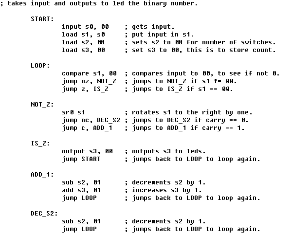
Figure 10: Task 11 program that displays the number of switches that are turned on in binary on the LEDs.