Homework 7 - UART
CE 433 Embedded Devices
2024 SpringName: Joel Nash
Email:
jxnash@gmail.com
Tasks:
1. In
section 2 use the debounce module to create a counter. When the
user press the button once, it shows a '1' on the seven segment
display. If the user keep pushing the button, the display
increments by 1 until 9 then it resets to 0.(25 points)
This task we are
required to design a counter module using the debounce module, and
displaying the numbers 0 - 9 on the seven segment displays. The
Figures below show the different modules used in this task:
'count_0_to_9' -
a module that takes in a button as an input and outputs a 4-bit
number. When the button is pushed one is added to the current sum.
If the sum equals 9 already when the button is pushed, then the
sum gets set to 0, to cycle 0 - 9.
'sev_seg_dis' -
a module that takes in 4-bit number and does a case function on
that input to set the 7-bit output for the seven segment display.
'debounce_0' - a
module that takes an button input and then debounces the button.
the debounced button then becomes the outputs, smoothing the
transition between the changes in the logic.
'button_counter_SSD_TOP'
- is the top module that uses the sub-modules, and wires them
together to make the counter, this is used to program the board.
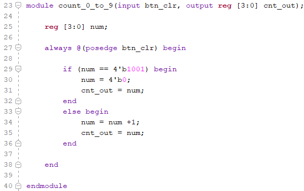
Figure 1 The
counter module that takes a button input, adds one to the sum or
sets sum to 0, when the sum equals 9, and outputs the 4-bit binary
number of the sum.
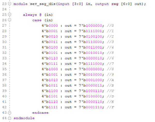
Figure 2 The
seven segment display module, taking in a 4-bit binary number and
output a 7-bit binary number to turn on the correlating lights on
the seven segment display.
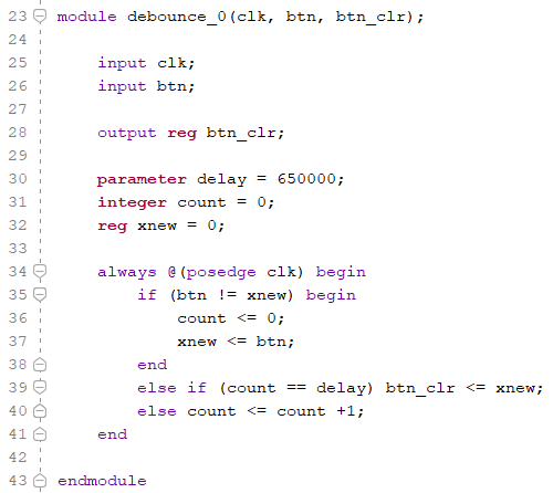
Figure 3 The
debounce module that debounces a button input and outputting the
debounce value.
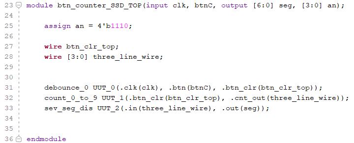
Figure 4 The top
module with the sub-modules, wires, and items that will be
programed on the board.
2.
Repeat the UART transmitter in Section 2 to show letters/symbols
in the serial monitor. (25 points)
In this task, we
were tasked to implement a transmitter. Within this the top module
will send an ASCII number to the serial monitor on the laptop. The Figures below show the different
modules used in this task:
'debounce' - a
module that takes an button input and then debounces the button.
the debounced button then becomes the outputs, smoothing the
transition between the changes in the logic.
'uart_tx_crtl'
- a module that prep that data to be transmitted, using
different states, 'RDY', 'LOAD_BIT', 'SEND_BIT', to transmit
bytes of information at a time.
'uart_tx_top'
- The top module for transmitting ASCII numbers to a serial
monitor. So when the button is pushed the ASCII value will
increase by one, this change will tracked on the serial monitor.
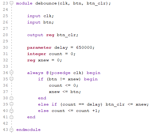
Figure 5 The
debounce module for debouncing the button used for transmitting
the ASCII numbers.
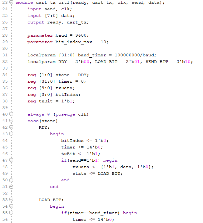
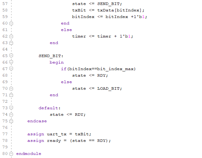
Figure 6 The
transmitting module the preps the data (ASCII numbers), using
different states, when the data in ready loaded and sent to send
the bytes of information.
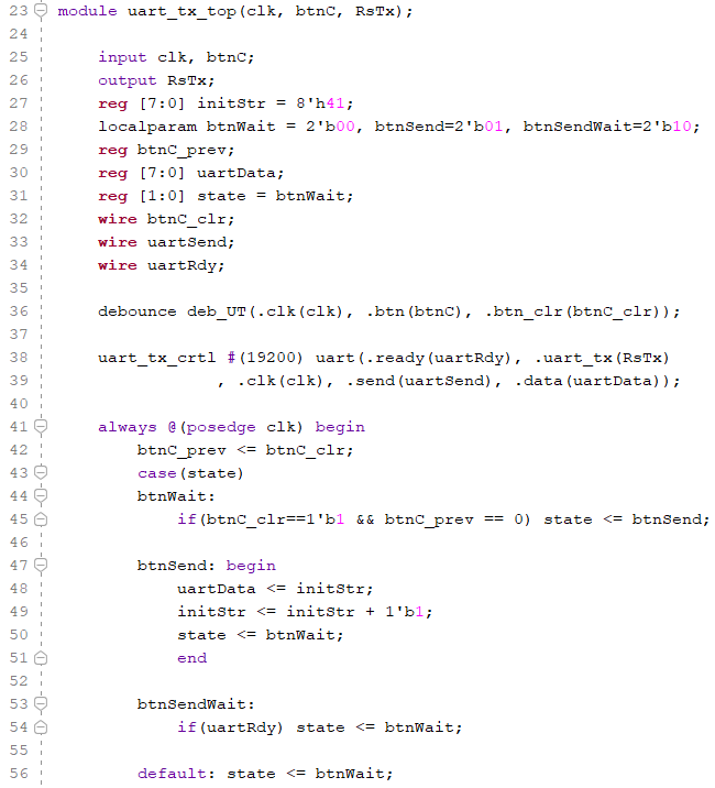

Figure 7 The top
module that is the transmits the information from the board to the
serial monitor. In this module the initial ASCII number is set to
'A' and then the ASCII number is sent to the serial monitor on the
laptop.
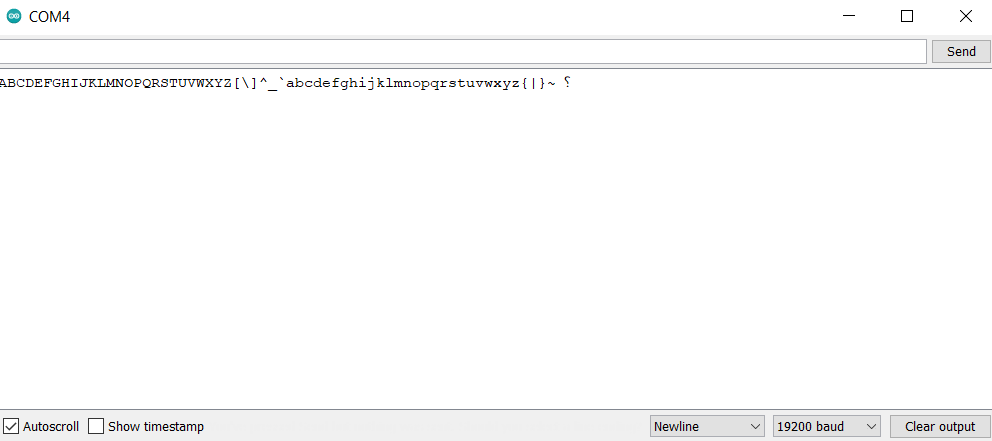
Figure 8 This is
the serial monitor showing the results of transmitting the ASCII
numbers from the board to the serial monitor.
3.
Repeat the work in Section 3. (25 points)
In this task, we were tasked to implement a receiver. Within this the top module will receive an ASCII number from the serial monitor on the laptop and display to the LEDs on the board. The board will display different things on the LEDs, count, error bit, parity bit, and the ASCII binary number. The Figures below show the different modules used in this task:
'debounce' - A
module that takes an button input and then debounces the button.
The debounced button then becomes the outputs, smoothing the
transition between the changes in the logic.
'uart_rx_crtl'
- A module that prep the data when received, using different
states, 'RDY' (says the bit is ready, checked, and received),
'START' (checks the timer and starts the timer in the middle of
data for sampling), 'WAIT'(waits for the timer to equal the end
of the data), 'RECEIVE' , 'CHECK' (parity bit checker that sets
or clears the 8Th LED) , when receiving data from the serial
monitor.
'uart_rx_top'
- The top module for receiving ASCII numbers from a serial
monitor. So when a character is typed into the serial monitor
the ASCII value is received on the board and displayed on the
LEDs, while also displaying the count of characters received,
the error bit, and the parity bit.
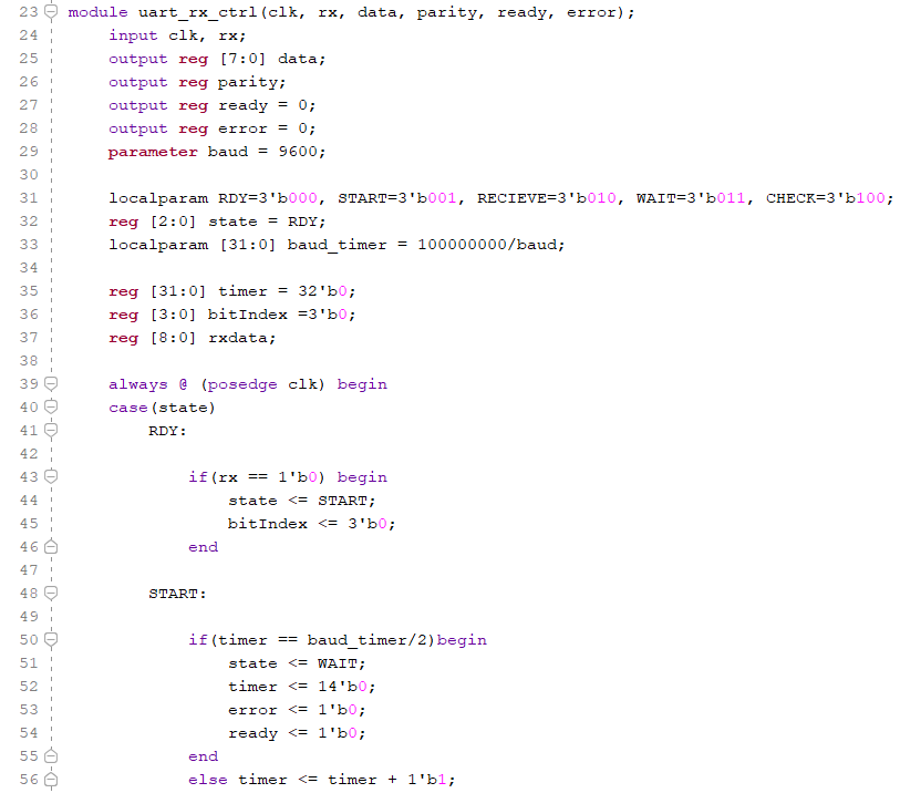
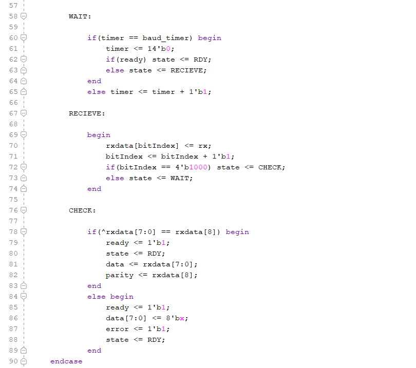

Figure 9 The
receiving data module, that takes in the data from the serial
monitor.
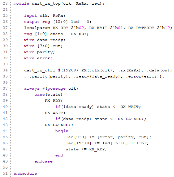
Figure 10 The
top module that connects the serial monitor to the board, and the
LEDs to different outputs, count, error bit,parity bit, and the
ASCII number.
4. Show
the numbers you typed in the serial monitor on one seven segment
display unit (less than 10). (25 points)
In this task, we were tasked to implement a transmitter and display the numbers typed in the serial monitor on one of the seven segment display unit (less than 10). The Figure below show the module used in this task (uses the same modules as the task above, but changes are shown in this figure):
'uart_rx_top_dis'
- The top module, this is the same as uart_tx_top just with the
added changes to display the numbers (0-9) typed into the
serial monitor onto one of the seven segment displays on the
board.
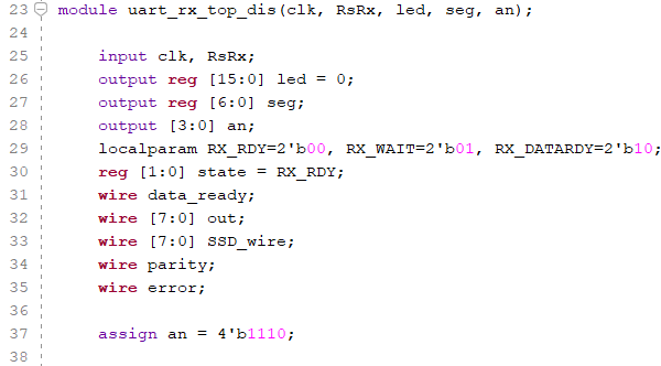
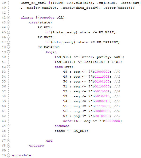
Figure 11 The
top receiving module that has the added seven segment display to
display the numbers typed in the serial monitor.