Homework 6 - Video Graphics
Array (VGA)
CE 433 Embedded Devices
2024 SpringName: Joel Nash
Email:
jxnash@gmail.com
Tasks:
Task 1:
Repeat the work in Section 2. Show the code, explanation, and a
demo video. (20 points).
Section 2 is
typing up the VGA module and the Top module in vivado. Then also
create a clock generator module using the IP Catalog at a
frequency of 25MHz, and create a distributed ROM to store the
image file. We were then able to display the image onto a monitor
using the BASYS3 board and VGA cord.
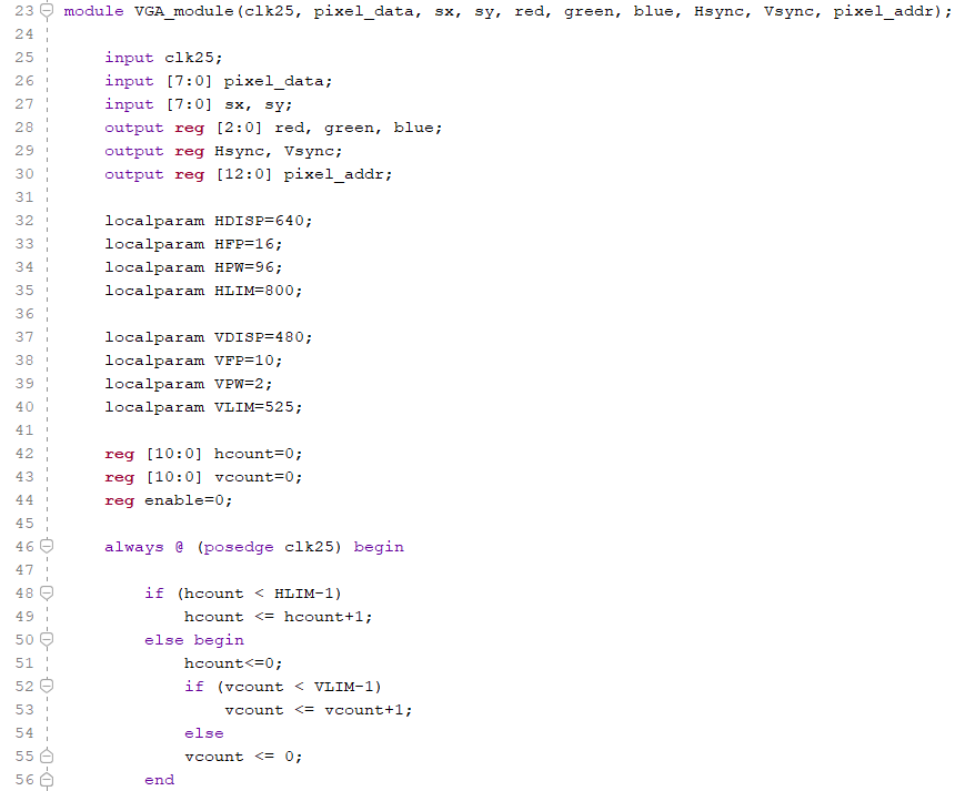
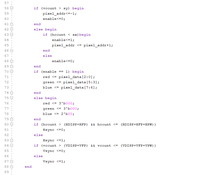
Figure 1: Vivado
code for the VGA module. working with the VGA through the
different horizontal values (HDISP: horizontal display, HFP:
horizontal front porch, HPW: (aka horizontal back porch), and HLIM:
horizontal limit) and vertical values (VDISP:
vertical
display, VFP: vertical
front porch, VPW: (aka vertical back porch), and VLIM:
vertical
limit)

Figure 2: Vivado
code of the VGA top module, setting the display limits (sx, sy),
using different modules, the clock module, memory storing the
image file, and the VGA module.
Task 2:
Replace the clock generator IP with a self-made clock divider
module that generates 25MHz clock. Demonstrate that it works for
the rest of the circuit.Show the code, explanation, and a demo
video. (20 points).
In this task, we
took the code from task 1, and replacing the IP clock generator of
25MHz with a self-made clock divider module that still works with
the code.
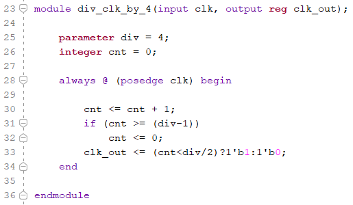
Figure 3: Vivado
code of a clock divider, that divides a clock by 4. (100MHz ->
25MHz).
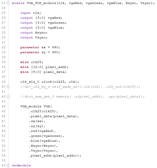
Figure 4: The
Top Module VGA that has the self-made clock divider implemented.
Task 3:
Complete the two examples in Section 3. Show the code,
explanation, and a demo video. (60 points).
In section 3 we
modified the code to display a blank white background on the
monitor, by using all four bits for each color, changing the all
to 4'b1111. then the second half of the task, we are switching
between three solid colors, red, green, blue, at one second
intervals.
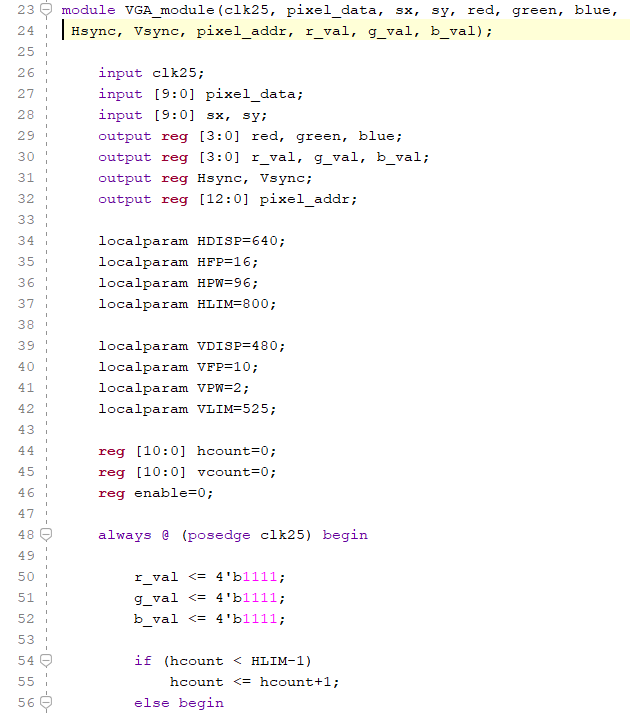
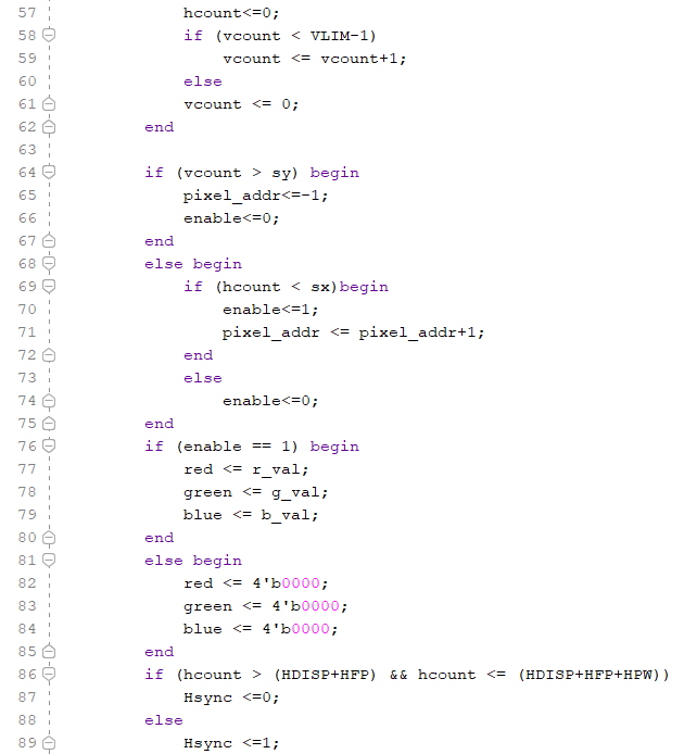
Figure 5: VGA
vivado code with the changing the output to the monitor to display
a blank white screen by setting the RGB values to 4'b1111.
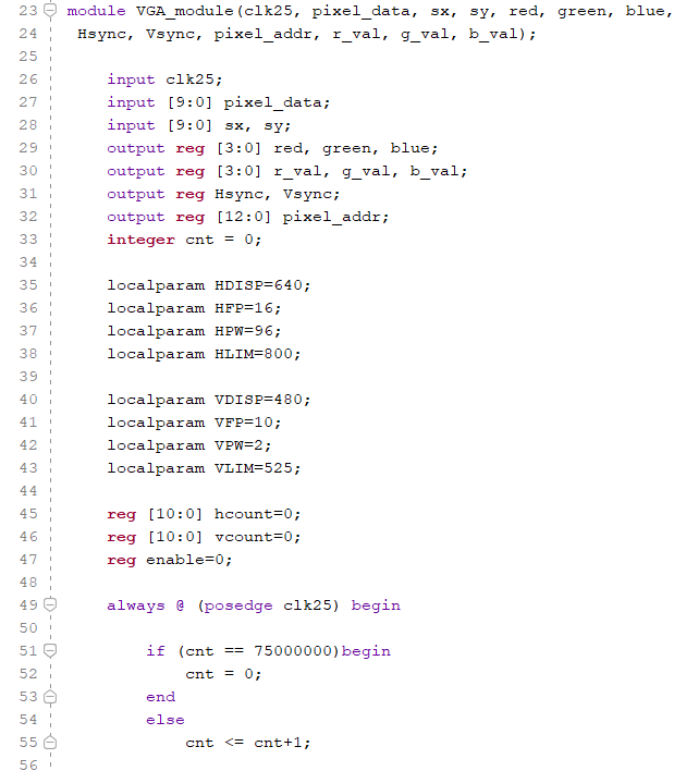
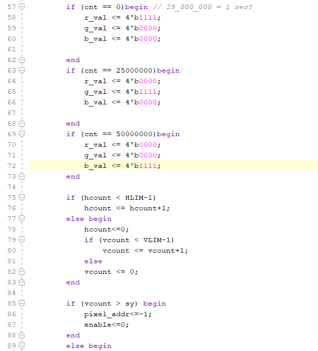
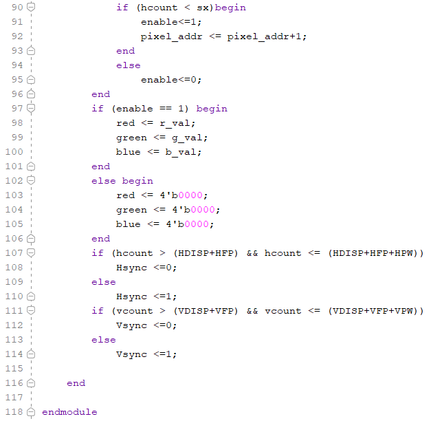
Figure 6: VGA
module code that changes the output to the monitor to display
three different colors, red, green, blue, iterating through them
at one second intervals.