Homework 3 - Combinational
Logic Blocks
CE 433 Embedded Devices
2024 SpringName: Joel Nash
Email:
jxnash@gmail.com
Tasks:
1. Repeat the
simulation of Half Adder and Full Adder in Section 1. Show the
code, code explanations, and simulation results in your report.
(10 points)
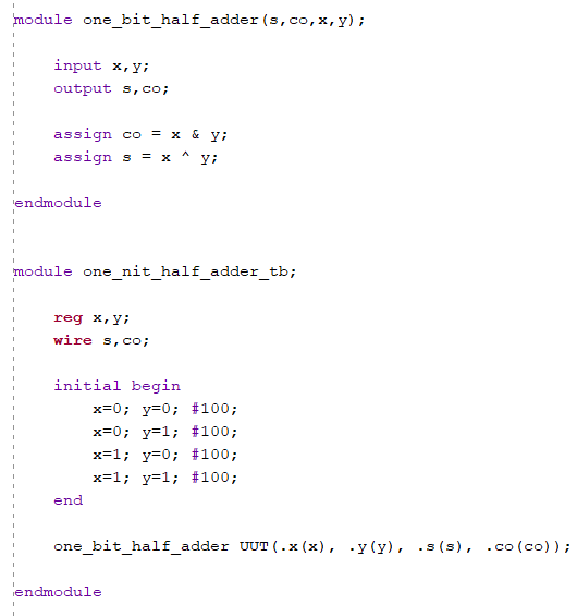
Figure
1: One bit half adder code. Changing the inputs every 100 np to
demonstrate adding and carry function.
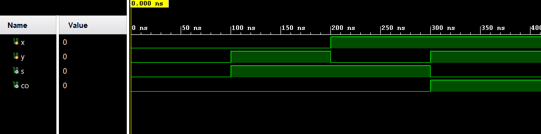
Figure 2: One bit half adder
simulation, showing the adding of 'x' and 'y' and the output 's'
and 'co'.
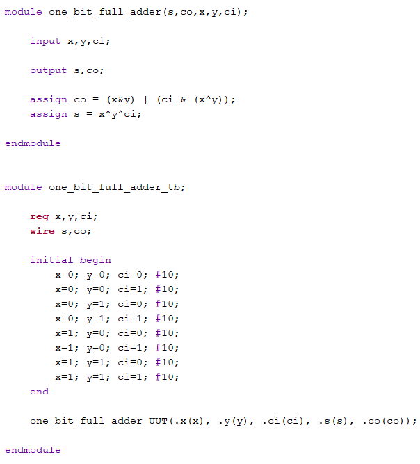
Figure 3: One bit full adder.
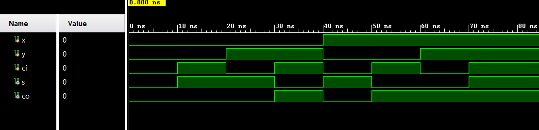
Figure 4: One bit full adder
simulation, showing the function of the inputs and the outputs.
2. Design the
testbench for the comparator in Section 2. Show the code, code
explanations, and simulation results in your report. (10 points)
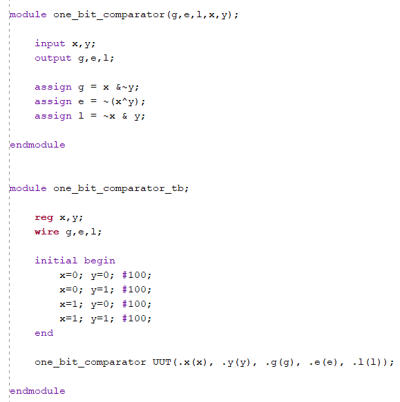
Figure 5: One bit comparator
code, changing the inputs 'x', 'y' to demonstrate how the
comparator works with the outputs 'g' (greater than), 'e' (equal
to), and 'l' (less than).
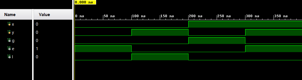
Figure 6: One bit comparator
simulation demonstrating the comparator.
3. Design the
testbench for the 4-bit comparator in Section 3. Show the code,
code explanations, and simulation results in your report. (10
points)
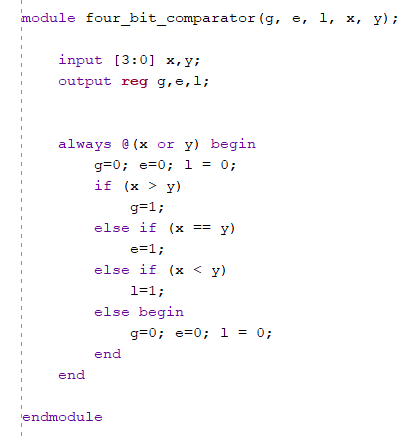
Figure 7: part 1 of four bit
comparator showing the logic for the comparator.
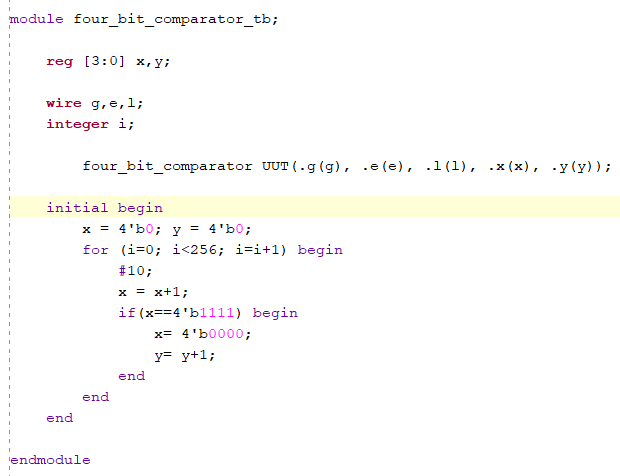
Figure 8: part 2 of four bit
comparator showing the test bench and the changing of the inputs
'x', 'y'.
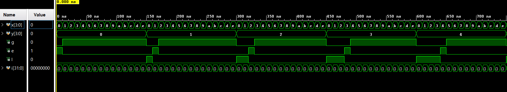
Figure 9: Four bit comparator
demonstrating the relationship between the inputs and the
outputs, showing if 'x' is greater (g), equal (e), or less than
(l) 'y'.
4. Implement
a 2-bit comparator on the Basys 3 board. Use sw as inputs and
led as outputs. Show the code, code explanations, and an
embedded Youtube video demonstration in your report. (10 points)
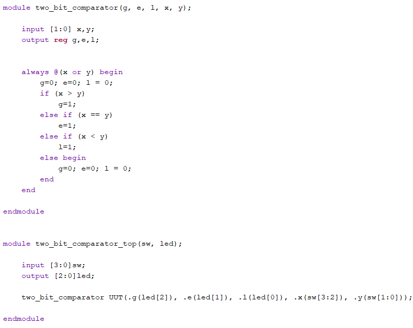
Figure 10: Two bit comparator
code for implementing onto the Basys 3 board.
5. In Section
4, design the testbench for the decoder and verify the logic in
simulation (use the Dataflow modeling method). Show the code,
code explanations, and simulation results in your report. (10
points)
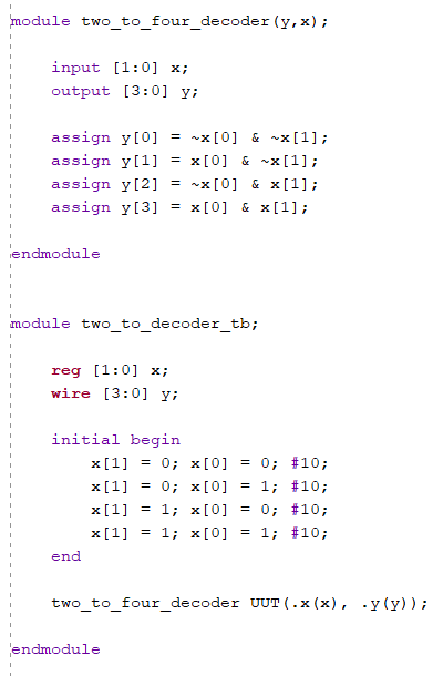
Figure 11: Two to four decoder,
using the data flow modeling to demonstrate the two to four
decoder logic.
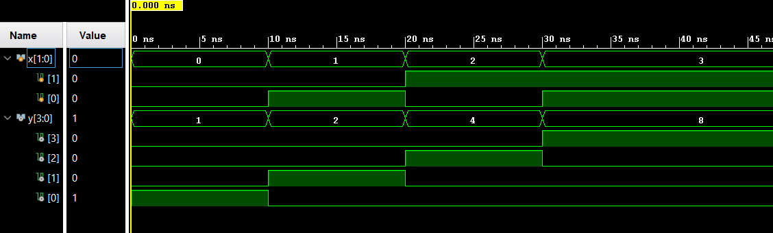
Figure 12: Two to four decoder
simulation showing the results of the code above.
6. In Section
5, for the 8x3 priority encoder, find Q2 and Q1, build the
module and verify the logic using simulations. Show the code,
code explanations, and simulation results in your report. (10
points)
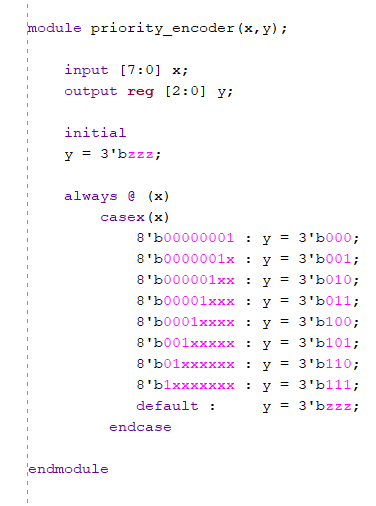
Figure 13: 8x3 priority
encoder, showing the setup for the encoder and using the 'x'
(don't care symbol) to insure that there is now confusion.
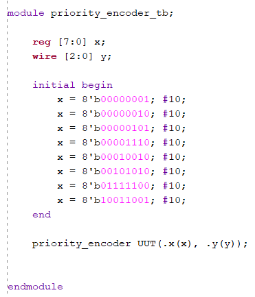
Figure 14: 8x3 priority encoder
test bench, setting the initial input 'x' to different values to
demonstrate the encoder and the use of 'x' to not confuse the
logic.
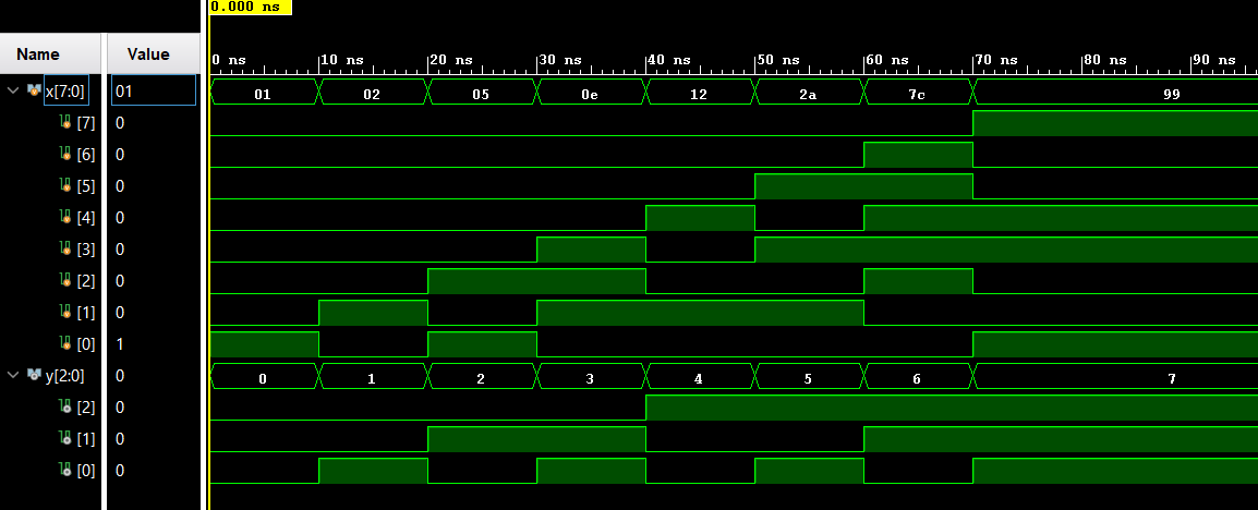
Figure 15: 8x3 priority encoder
simulation showing the results from the test bench logic.
7. Derive the
logic expression of a 4-1 multiplexer. Show the process on a
paper, insert it as an image into your report. (10 points)
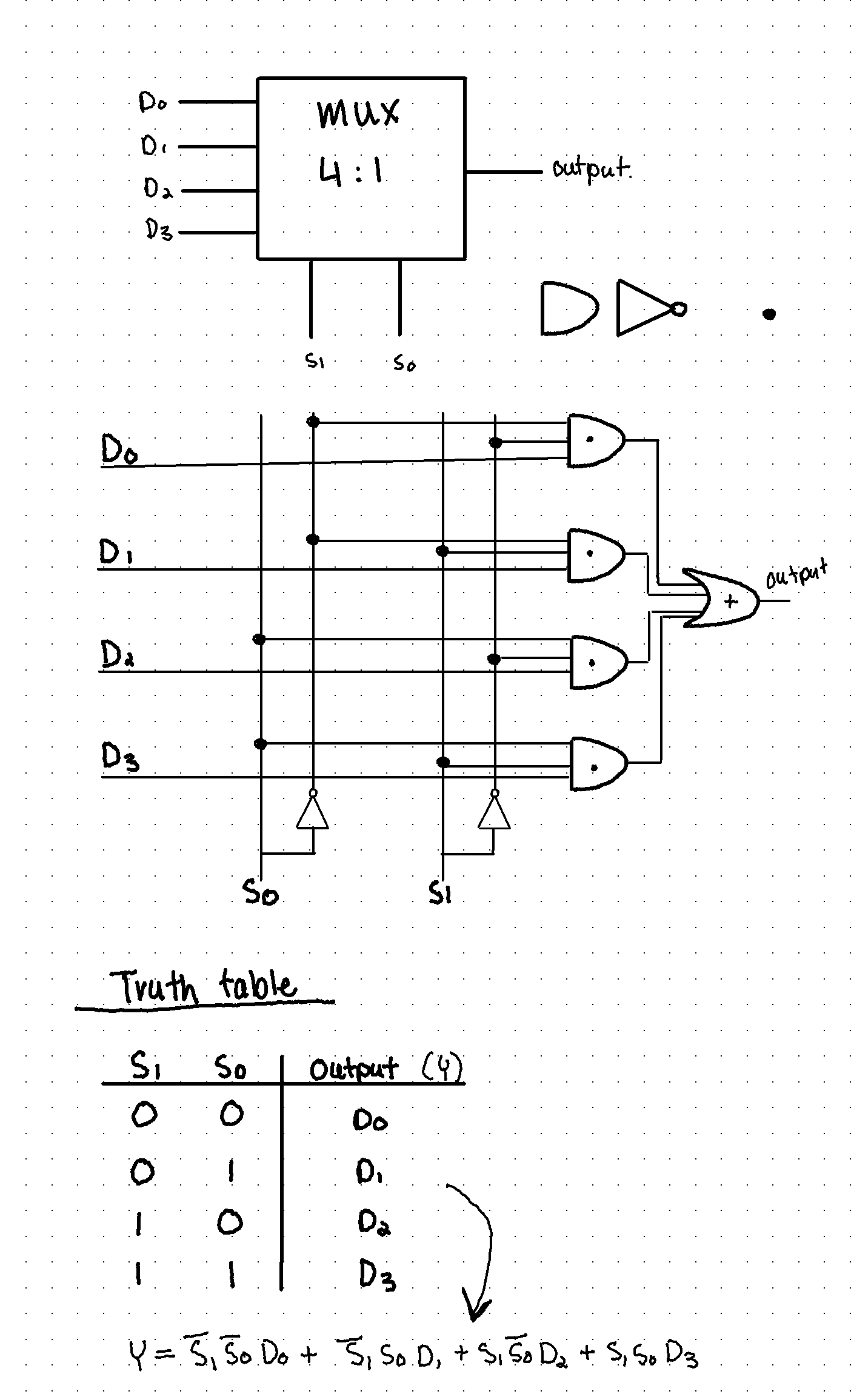
Figure 16: the logical
expression of a 4-1 Multiplexer, showing the logic gate and
truth table and resulting logic.
8. In Section
6, implement a 4-1 multiplexer on your Basys 3 board. Show the
code, code explanations, and an embedded Youtube video
demonstration in your report. (10 points)
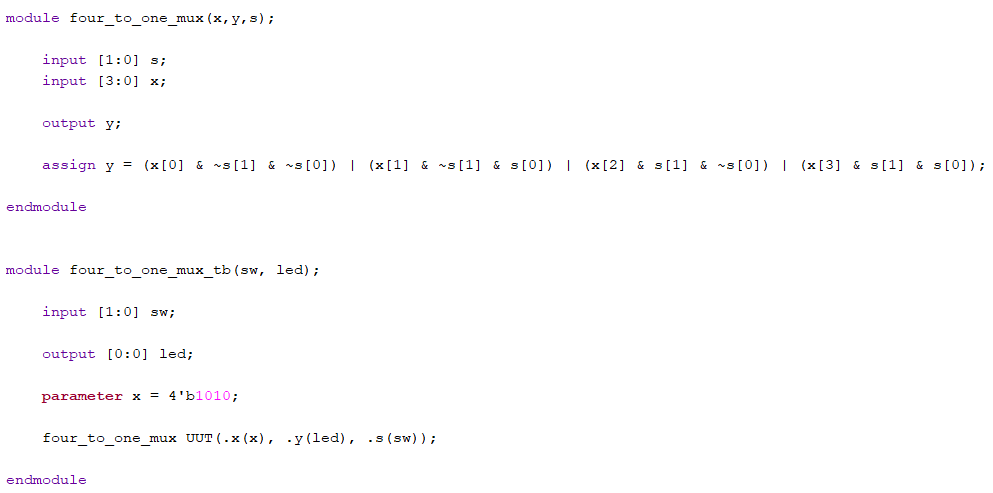
Figure 17: 4-1 Multiplexer code
setup for implementing onto the Basys's 3 board using switches
and leds, while setting the input value to '1010' to show the
mux logic.
9.
Design/verify an even parity generator and checker in simulation
respectively. Implement an even parity checker on your Basys 3
board - use sw as inputs, use leds as output indicators. Show
the code, code explanations, and an embedded Youtube video
demonstration in your report. (10 points)
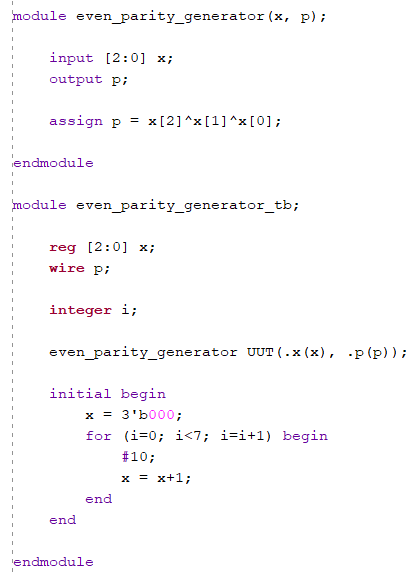
Figure 18: Even parity
generator code, with the logic taking in values from 'x' and
then using the output p to make 'x' even.
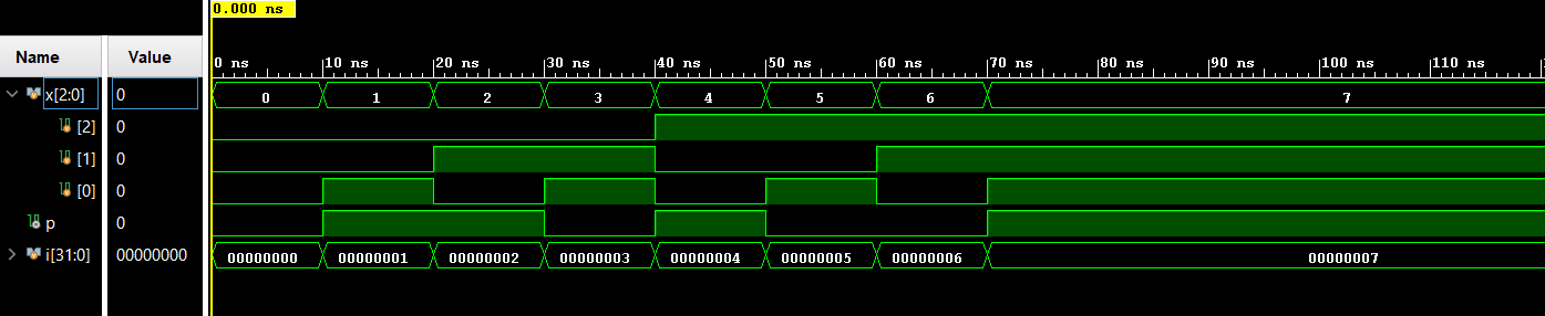
Figure 19: Even parity
generator simulation of the working even generator with no
modifications.
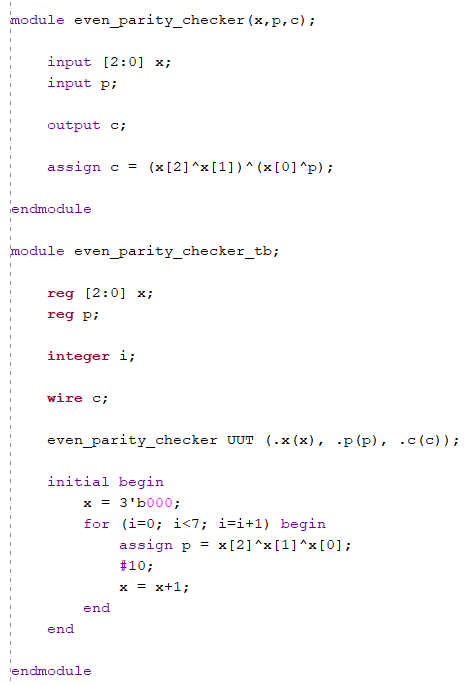
Figure 20: Even parity checker
test bench code, that changes the input 'x' to show the result
of the checker logic.
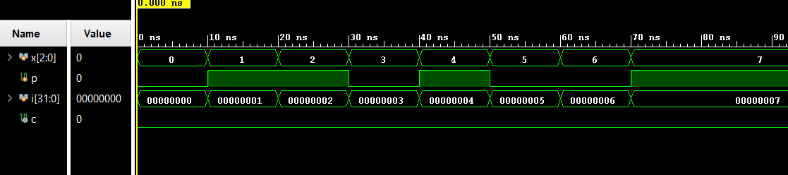
Figure 21: Even parity checker
test bench simulation, showing that the logic is working as
there is no changing the output 'c'.
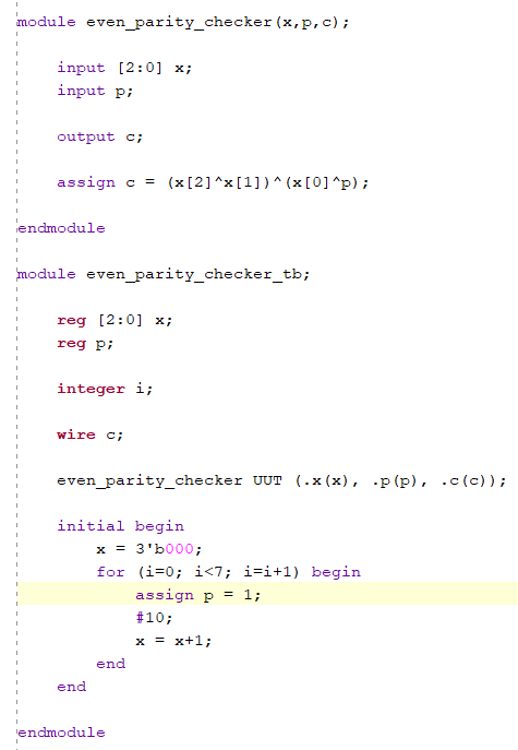
Figure 22: Even parity checker
test bench code, with a slight modification of just setting the
input 'p' to 1, to show the checker when there is an error.
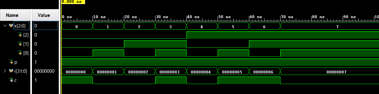
Figure 23: Modified even parity
checker simulation showing the results of the set 'p' input and
the working checker logic.
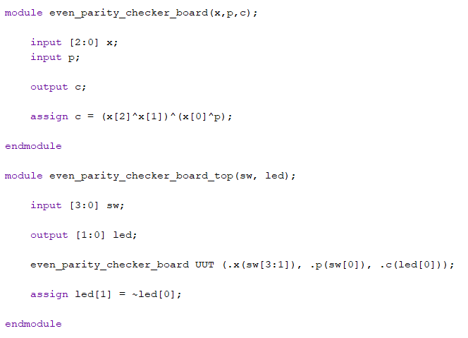
Figure 24: Even parity checker
that will be implemented onto the Basys board.
10. Implement
the design in Section 8 and Section 9 on your Basys 3 board.
Show embedded Youtube video demonstration on your report. Show
the code, code explanations, and an embedded Youtube video
demonstration in your report. (10 points)
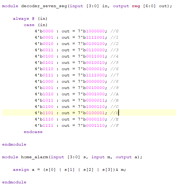
Figure 25: Code for the 7
segment decoder (takes 3-bit input and outputs 7-bit number for
the display), and the home alarm logic.
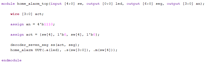
Figure 26: Home alarm code that
sets the input switches and outputs, leds and the
7-segment/analog display.

Figure 27: Code for the
7-segment analog display, and car park counter.
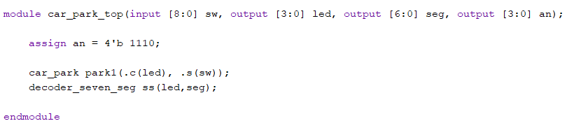
Figure 28: Car park code to set
input switches and output leds, and 7-segment analog display.