Homework 2 - Data types,
Operators, and Combinational logic
CE 433 Embedded Devices
2024 SpringTasks:
1. Work on the following
problems: (20 points)
a. What are the fixed point representations of the following
decimal numbers? Display your calculations and results on a
paper and take a picture of it as an embedded image on your
website.
20.25 in UQ16.16
128.5 in UQ16.16
0.125 in UQ.16
-38.125 in Q15.16
-50.0625 in Q15.16
b. What are the floating point representations of the
following decimal numbers? Display your calculations and
results on a paper and take a picture of it as an embedded
image on your website.
0.141 in half precision/format
3.625 in half precision/format
-15.25 in half precision/format
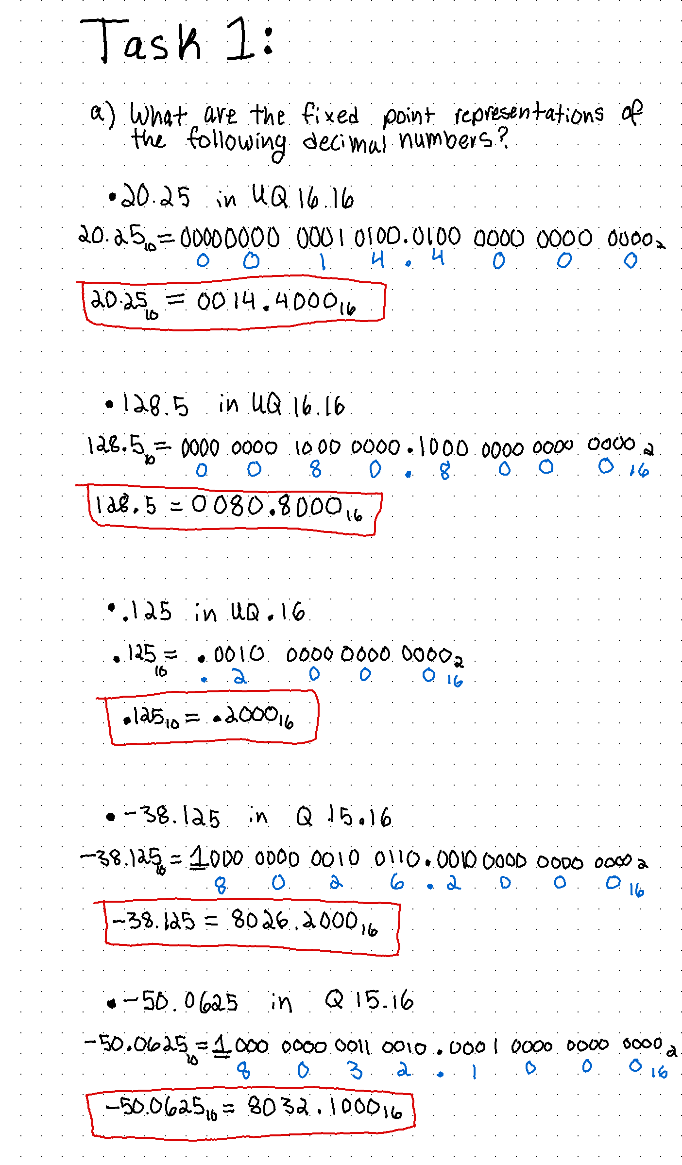
Figure 1: Showing the fixed point representation asked in Task 1 (a), in this figure shows the questions worked through.
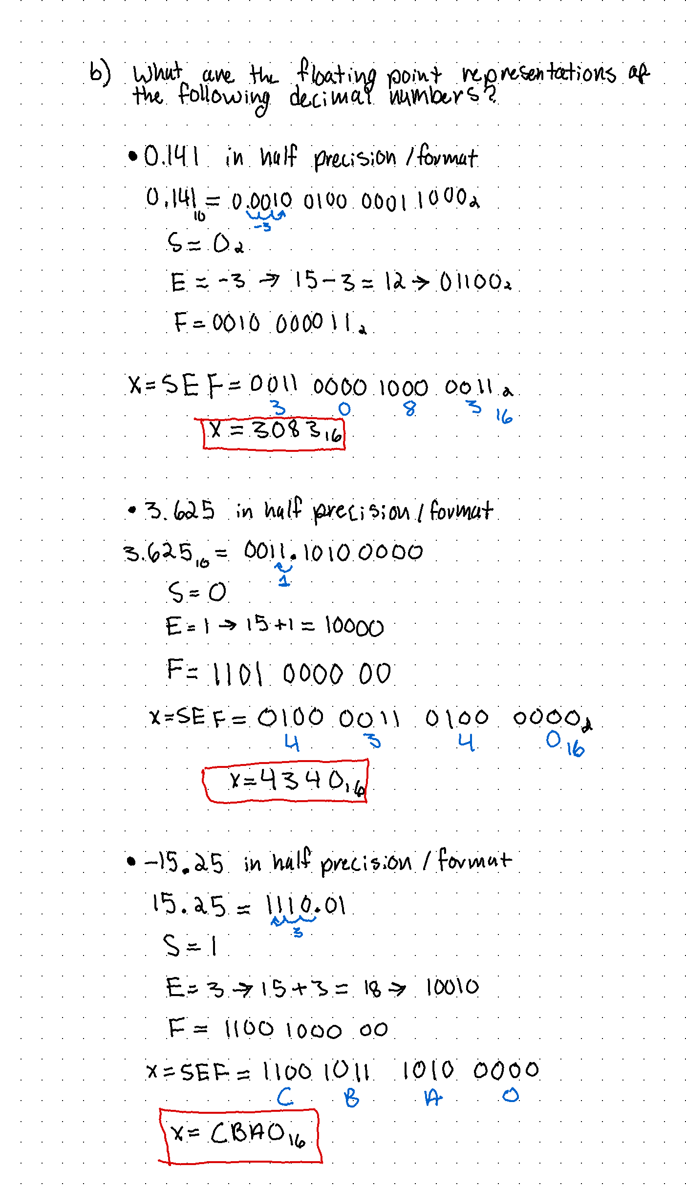
Within Task 1 we work through the two
methods to represent a binary number, fixed point representation
and float point representation, while taking into account if it
is signed/unsigned, the fractional part and the number of digits
to go out to.
2. Repeat the simulation work in Section 5. Demonstrate your
results in embedded videos on your website. (20 points)
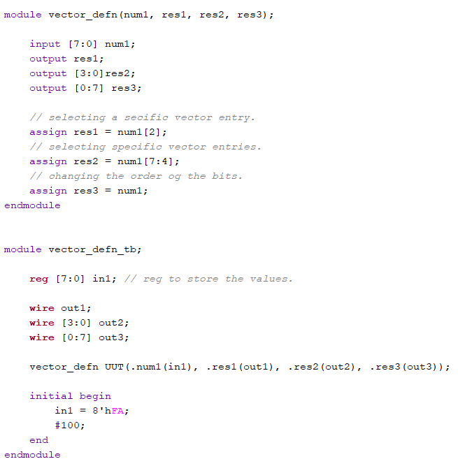
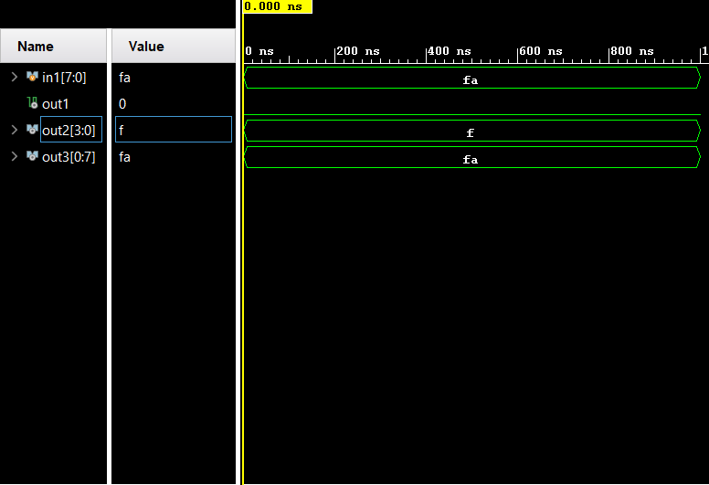
Figure 4: Simulation of the code shown above, showing the output of the vector.
3. Repeat all the FPGA experiments in Section 7. Demonstrate
your results in embedded videos on your website. (30 points)
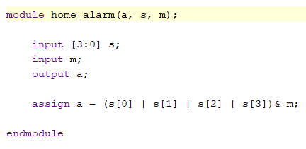
Figure 5:Vivado code for the home_alarm, showing the combinational logic.
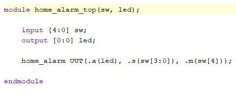
Figure 6: code showing the setup for the input switches and the output LEDs.
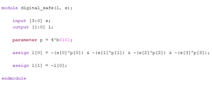
Figure 7: Vivado code for a digital safe showing the logic and the in/outputs.

Figure 8: setup code for the digital_safe with input switches and output LEDs.
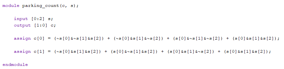
Figure 9: Vivado code showing the logic for parking_count and how that counts the spots taken.
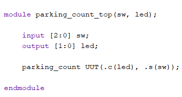
Figure 10: parking_count setup code for input switches and output LEDs.
4. Design a simple
digital system using the similar combinational logic design
methods shown in Section 7. Explain what the system is, show
the design files, demonstrate it on your FPGA. Demonstrate
your results in embedded videos on your website. (30 points)
My simple
digital system is an Available parking spot counter,
using the same concept as the parking_counter in Task 3. This
code improves on it a little by adding the feature of showing
how many parking spots are left in the lot. In my code I set the
maximum number of spots to 16 spots, and as the number of cars
(switches) increases ,(goes from left to right), the LEDs
decreasing indicate the number of spots left in binary.
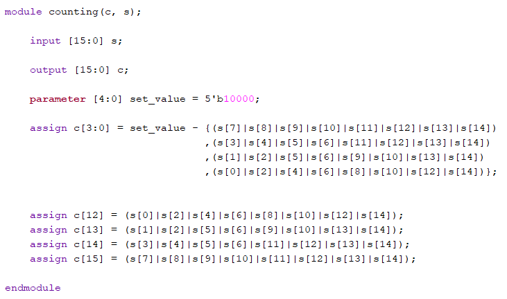
Figure 11: Vivado code for Available parking spots left, showing the logic and the preset (parameter) parking max.
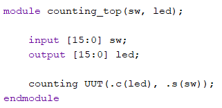
Figure 12: Setup code indicating the input switches and the output LEDs, for available parking spots.