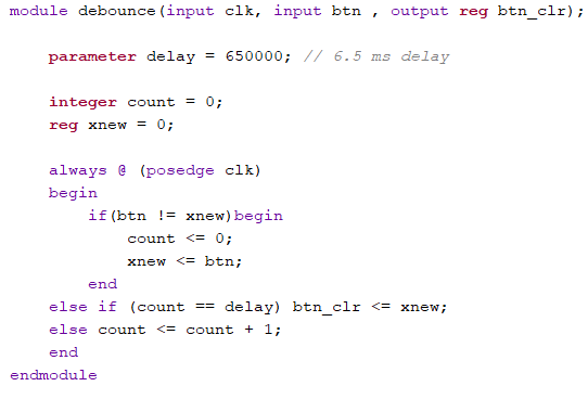
Figure 1: This vivado code is
the debounce function, that takes an input an then changes the
output to the opposite logic. In this case the input is a
button, and at every positive edge of the clock cycle, if the
button does not equal xnew, count is set to 0, and xnew set to
the value of the button. If they are equal then btn_clr is set
to xnew, and the then count is incremented.
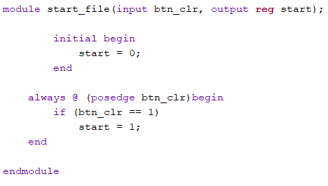
Figure 2: This vivado code is
the start function, that just takes an input (the btn_clr output
from the debounce function) and then as that the input changes
the logic is checked, if input = 1, then the variable 'start' is
permanently to 1.
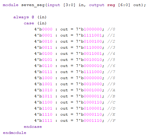
Figure 3: This vivado code is
just for the Seven Segment Display. Taking in a 4-bit input that
then is decoded into 7-bit binary numbers that represent the 'G
to A' LEDs on the digital displays.
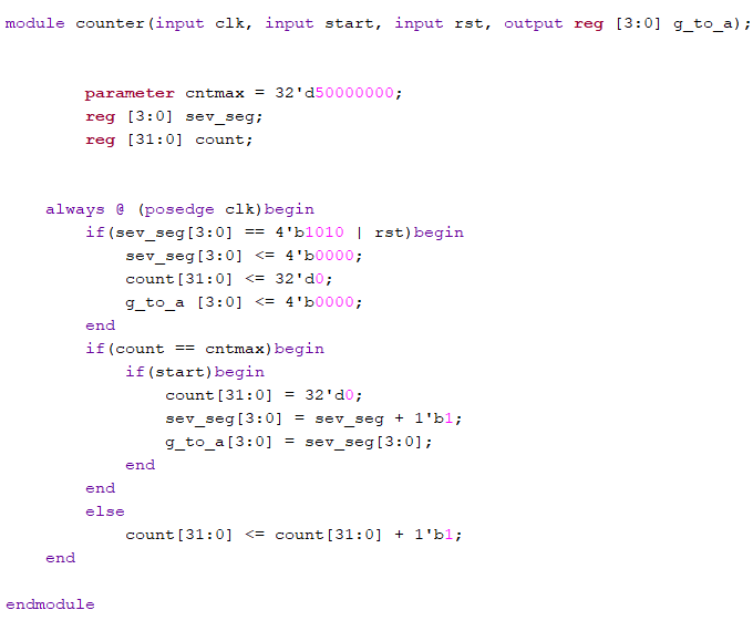
Figure 4: This vivado code is
the counter function that outputs the 4-bit binary number that
is used for the seven segment display. The code uses the
positive edge of the clock cycles to iterate through 0-9 on the
display, using a delay of half a second between numbers. The
count, sev_seg, and the output g_to_a are all reset to 0 when
the sev_seg = 10, and or if the right button(rst output from
another debounce function) is pressed.
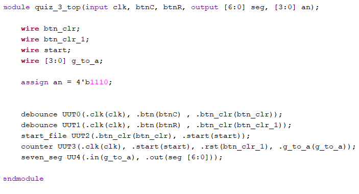
Figure 5: This is the final
vivado code, The Top module /Testbench. This piece of code
brings together all the another functions, linking them together
with wires.
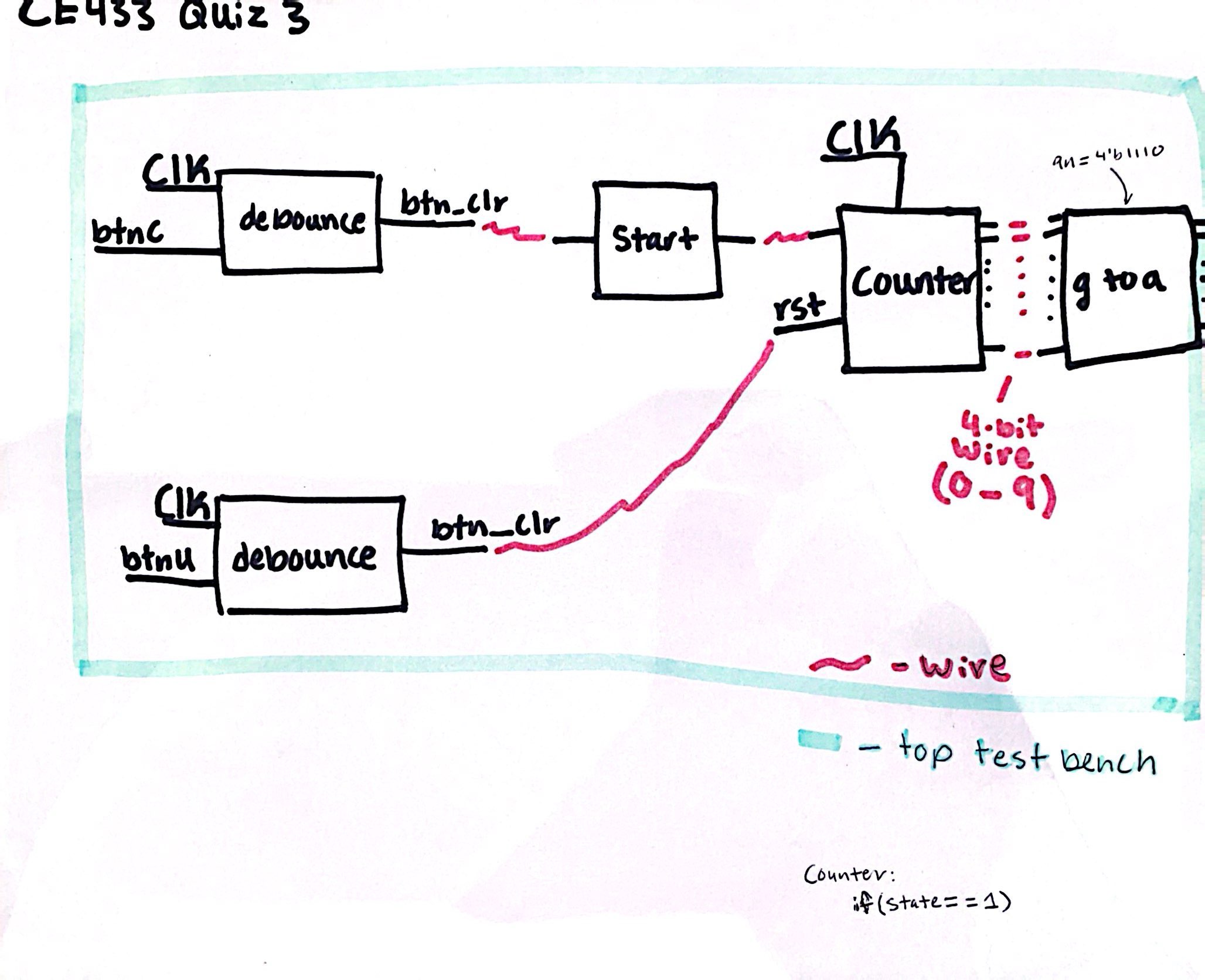
Figure 6: This is a visual
representation of the top most module, and how they all work
together.
Video 1: In this video I
demonstrate counting from 0 to 9. First I show that none of the
other buttons effect the display until the center button is
pressed, and then the count starts. Going from 0 to 9 and then
repeating when it reaches 10 or when the right button is
pressed.