Lab 5 - A 3-bit Adder/Subtractor for 2's Complement Signed Binary Numbers
CE 433 Embedded Devices
2024 SpringTasks:
Step 1: (30 points)
Use switches as the 3-bit inputs, use 'leds' to show the
binary results.
In this task we were assigned to make a 3-bit full adder and display the result using the LEDs on the board. The figures below show the different modules used in this task, and the video showing the code in action.
'one_bit_FA' - A one bit full adder module that takes in two bits, and applies logic to get the sum and the carry out of the two bits.
'three_bit_adder' - Is a module that
takes three different 'one_bit_FA's and wires them together to
get a 3-bit full adder. That takes 3-bits and and adds them
together, calculating the sum, and the carry out, while also
checking if there is an over flow, by XOR-ing 'CO_1' and 'CO_2'.
'T1_3bit_adder_TOP_mod' - Is the top
module that sets the LEDs and the switches that are used to set
the bits and display the result.
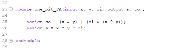
Figure 1: One bit Full Adder, and outputs the sum and the carry out bits.
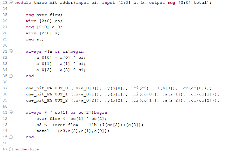
Figure 2: 3-bit Full Adder that takes
three one bit full adders and wires them together. This also
checks for over flow.
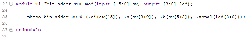
Figure 3: The 3-bit Top module that
sets the switches and LEDs to set bits and display results.
Step 2: (30 points)
Use switches as the 3-bit inputs, use seven-segment displays
to show the decimal result, make sure have the 'minus' sign in
front of the decimal number if the result is negative.
In this task we were assigned to make a 3-bit full adder and display the result using the seven segment displays on the board while taking into account of negative values. The figures below show the different modules used in this task, and the video showing the code in action. Some of the same modules are used in this task, 'one_bit_FA', and the 'three_bit_adder' modules.
'SSD_w_neg' - Is a seven segment
display module that displays the resulting binary number of the
full adder onto the digital displays. The module takes into
account of the most significant bit from the result to determine
the sign of the binary number, MSB == 1 equals negative, MSB ==
0 equals positive.
'T2_3bit_adder_SSD_TOP_mod' - Is the
Top module that sets the switches used to set the bits and the
segment displays that are enables to diplay the result.
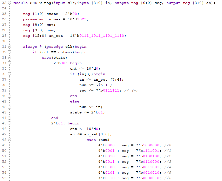
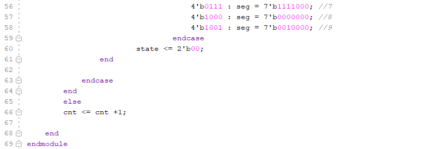
Figure 4: The seven segment display module that displays the result from the 3-bit adder. That also takes into account of the MSB to determine the sign of the binary number and displays that accordingly.
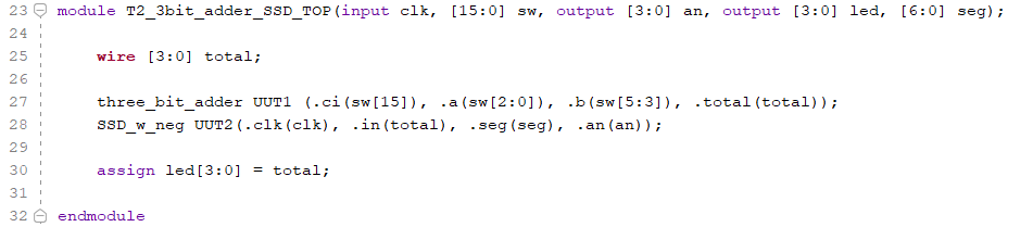
Figure 5: The 3-bit adder module that
displays the results and the sign on the seven segment displays.
This module enables the switches to set the bits and enables the
displays to show the results on the segment displays.
Step 3: (40 points)
Use Serial In Parallel Out (SIPO) to input two 3-bit numbers
[2:0] A, and [2:0] B, into the registers, then use one switch
to trigger the computation.
In this task we were assigned to
implement a Serial-in Parallel-out into task 2, instead of using
6 different switches. The figures below show the different
modules used in this task, and the video showing the code in
action. Some of the same modules are used in this task,
'one_bit_FA', 'three_bit_adder',
and the 'SSD_w_neg'
modules.
'debounce'
- a module that takes an button input and then debounces the
button. the debounced button then becomes the outputs, smoothing
the transition between the changes in the logic.
'sipo_6bit_out'
- Is the serial-in parallel-out module, that takes in one bit
per rising edge of the 'clock', and once the count has reached 5
rising edges the module will output the 6-bit number.
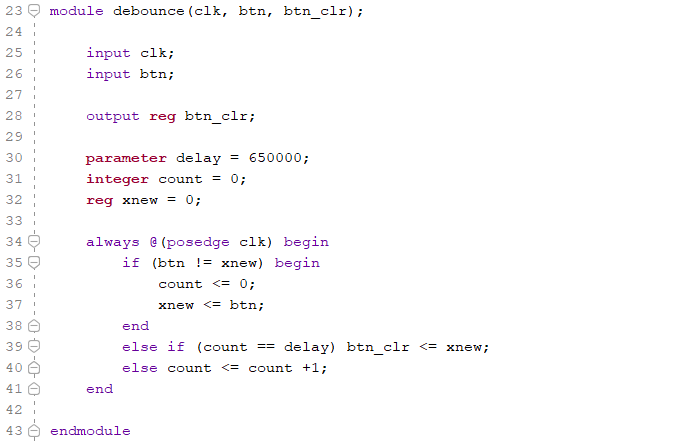
Figure 6: A debounce module that
debounces the input switch and outputs the debounced value.
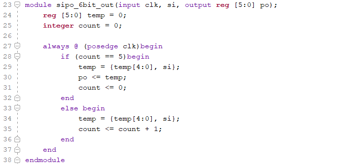
Figure 7: The serial-in parallel-out
module that takes in one bit per clock rising edge and outputs a
6-bit binary number.
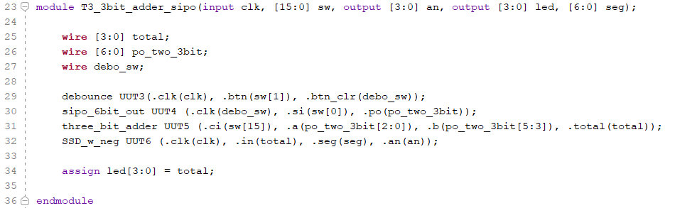
Figure 8:The 3-bit adder top module
with serial-in parallel-out input output.