Lab 4 - Combinational Logic
Blocks
CE 433 Embedded Devices
2024 SpringName: Joel Nash
Email:
jxnash@gmail.com
Tasks:
Task 1: Think
about how many states the two-way traffic lights may have for
each cycle. The green light on one side turns yellow and then
turns red before the other light changes to green from red.
Draw the
truth table for all the states in one cycle of the traffic light
change. Simplify the logic equations for each light using the K
map. Design the Verilog model and the test-bench, show the
simulation results in Vivado. Use 6 leds on your Basys 3 board
to implement the design. Show the demo video for credits. (50
points)
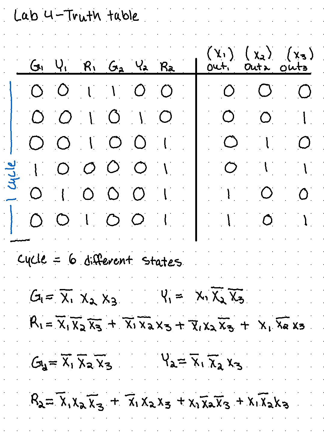
Figure 1: Truth
table of all the states of the traffic lights, and then the
resulting logic equations for each light (Green 1, Yellow 1, Red
1, Green
2, Yellow 2, Red 2).
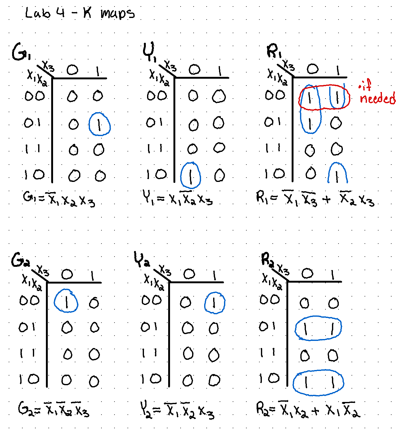
Figure 2: K-Map
of the traffic lights and the resulting simplified logic
equations.
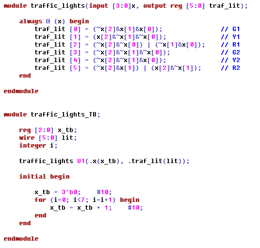
Figure 3:
Verilog module code with the logic equations for the traffic
lights, and the test-bench with a changing input to demonstrate
the logic and the changing of the lights.
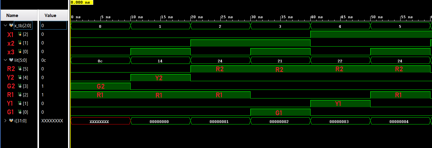
Figure 4: The
resulting simulation of the traffic light module, showing the
changing of the lights.
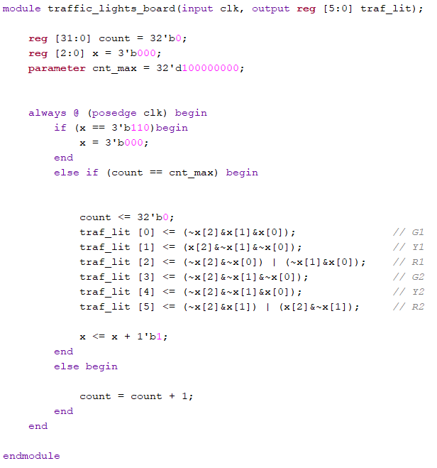
Figure 5: Vivado
code for implementing the changing logic of the lights onto the
board using the LEDs as the outputs, changing the state of the
lights every one second.
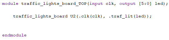
Figure 6: The
top module of the traffic light module, to program the board.
Task 2: While
the first problem cycles through all states with the same
duration, during rush hours, the busy road has a longer duration
for the green light than the red light. Use a switch to trigger
the rush hour mode, which keeps one of the green lights ON for
double the duration compared to the other road. Show the code,
code explanation, and demo video in your report. ( 50 points)
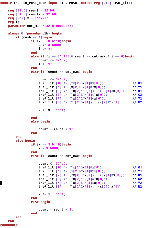
Figure 7: Module
code for the "Rush Traffic Mode" for the changing light logic.
This takes the module from earlier, and implementing a rush mode
that makes one traffic light last twice as long when a switch is
turned on.
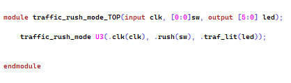
Figure 8: The
TOP module of the "Rush Traffic Mode", to set the switch and LEDs.