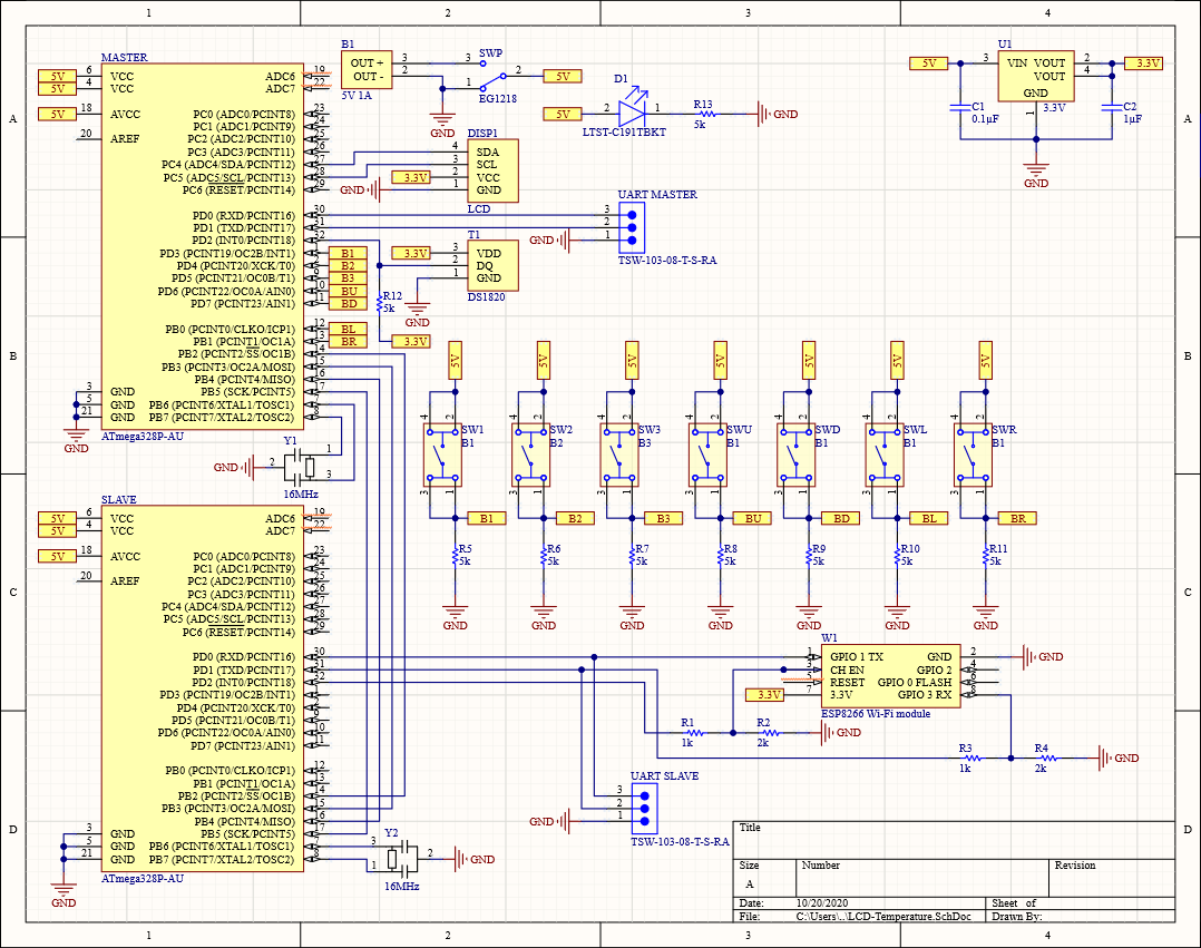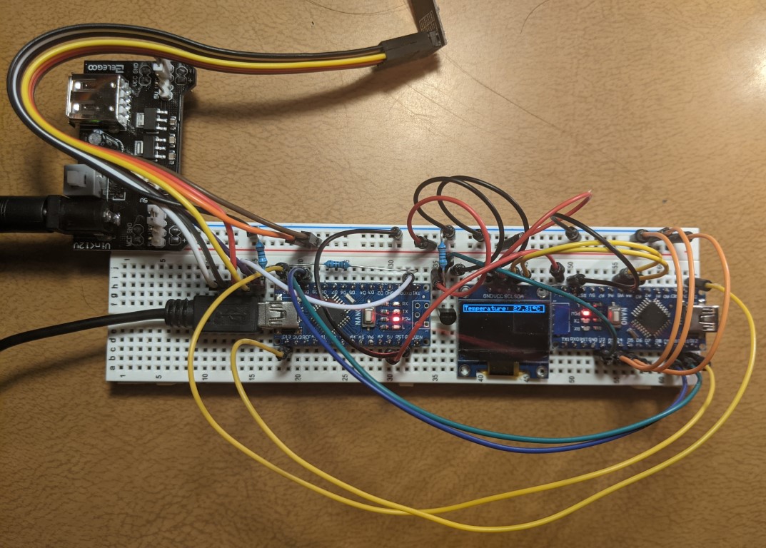
Fig. 1 The device on a breadboard. the left Arduino is the slave and the right is the master. The three orange wires on the left can be pulled high or low for user input.
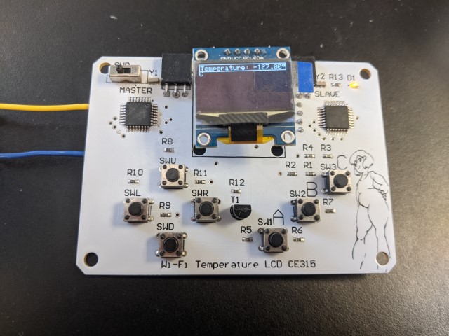
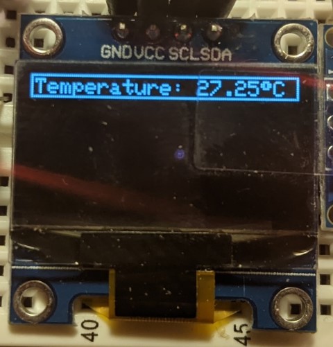
| (a) Main |
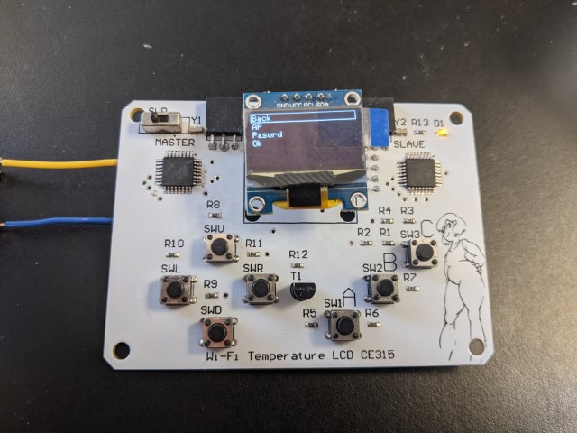
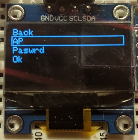
(b) Menu |
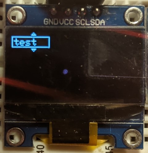
(c) Editor |
 |
 |
 |
|
AT+RST AT AT AT+CWMODE=1 AT+CWJAP="Guest","" AT+CWJAP="Guest","" AT+CWJAP="Guest","" AT+CIPMUX=1 AT+CIPSTART=0,"TCP","api.thingspeak.com",80 AT+CIPSEND=0,53 GET /update?api_key=GVDN5WA12ZF3ZCU3&field1=27.44 AT+CIPCLOSE=0 AT+CWQAP AT+RST AT AT+CWMODE=1 AT+CWJAP="test","" AT+CWJAP="test","" AT+CWJAP="test","" AT+CWJAP="test","" AT+CWJAP="test","" AT+CWJAP="test","" AT+CIPMUX=1 AT+CIPSTART=0,"TCP","api.thingspeak.com",80 AT+CIPSEND=0,53 GET /update?api_key=GVDN5WA12ZF3ZCU3&field1=27.19 AT+CIPCLOSE=0 |