Power Supply for MCU PCB
Jesse Duran
Fall 2020
CE 351
Introduction:
For this project we created a powersupply PCB using Eagle PCB. This
included making our our componant library and preparing our files for
manufacturing.
Schematic
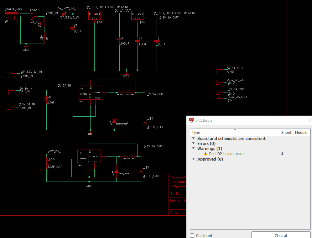
Figure 1. Completed schematic with variable power output. ERC clean
Board Layout
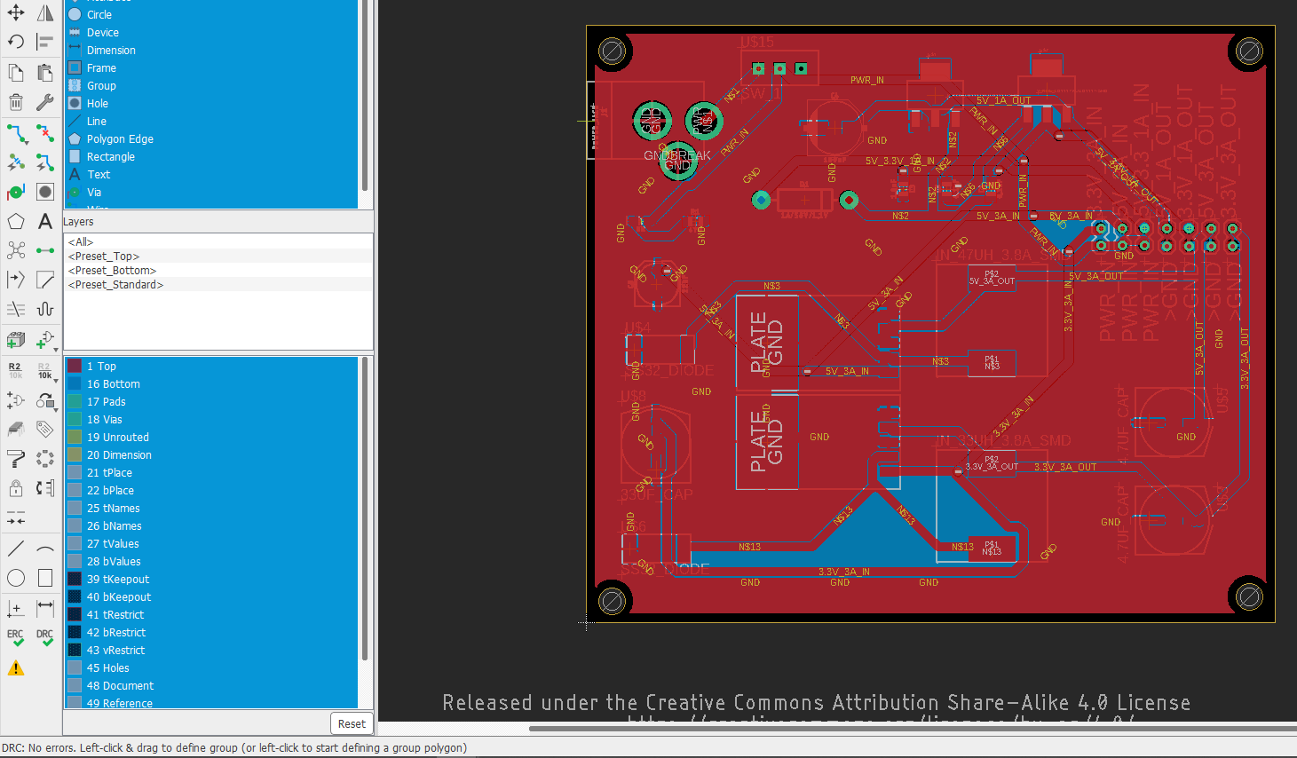
Figure 2. Completed bored wired and ratnested. DRC clean
Gerber Files
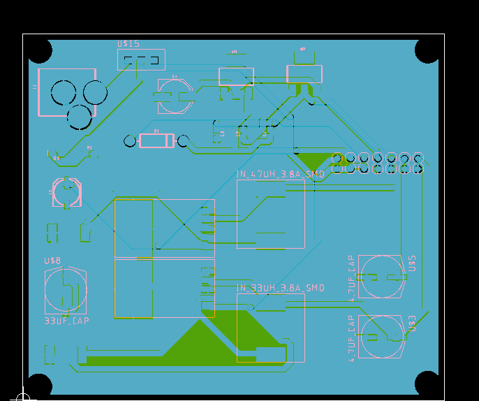
Figure 3. Completed gerber files Blue-Top layer. Green-Bottom layer. Pink-silkscreen
Library:
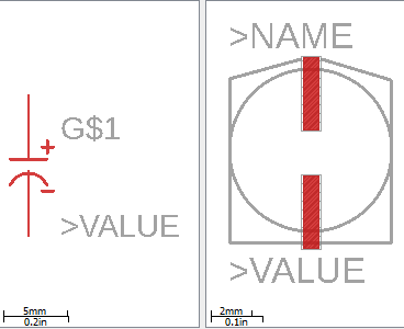
Figure 4. 4.7uF/33uF capactior
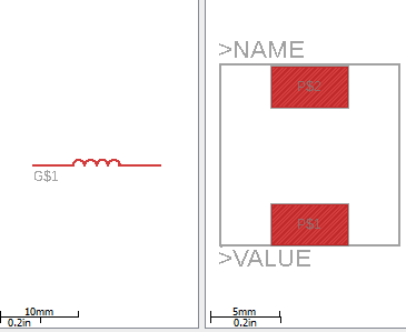
Figure 5. 33uH inductor
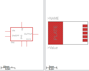
Figure 6. LM2596

Figure 7. Power Jumper for power output selection
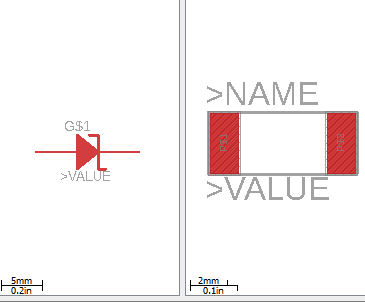
Figure 8. Schottky Diode

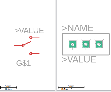
Figure 9. Power Switch
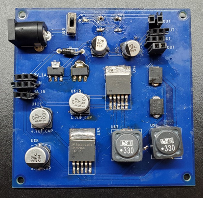
Figure 10. Soldered board
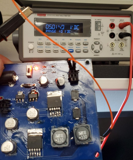
Figure 11. 5v 1A output
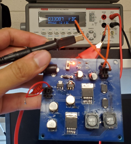
Figure 12. 3.3V 1A output
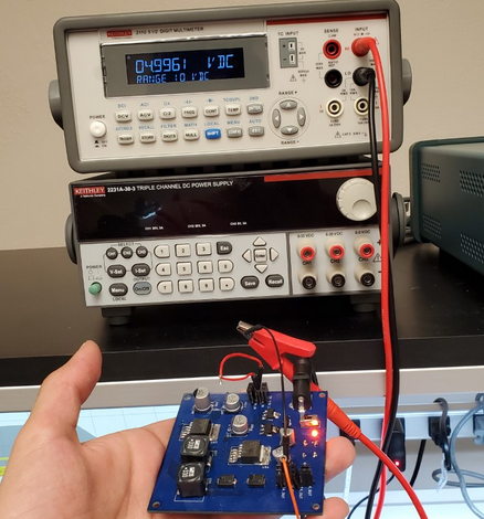
Figure 13. 5V 3A
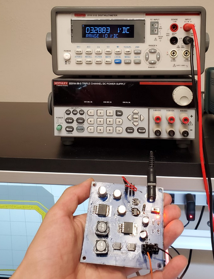
Figure 14. 3.3V 3A
Discussion
Through this PCB creation process we learned how to pick
appropriate
componants for our project. We learned how to use Eagle PCB to create
custom librarires and layout a PCB. The trial and error invlolved with
this project allowed for the skills learned in Networks I to be
re-enforced. Soldering the PCB provided good experience in soldering
0603 componants and taught me how to use the blower. Troubleshooting
the PCB made me dig into the data sheets of the voltage regualtors and
deepened the understanding of the overal performace. Overall the
powersupply was a fun project that was rewarding to see working.