Name: Ian Van Horn Email: imvanhorn1@gmail.com
Lab 5 3 bit 2's compliment adder/subtractor
This lab
uses more complex logic and clocked combinational blocks incorperated
with an SSD
This lab requires Vivado
Task 1: Use switches as binary
inputs and LEDs to dispaly outputs.(30 points).
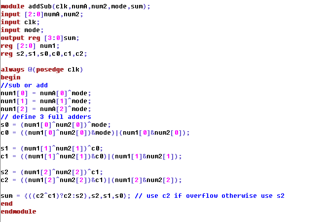
Figure 1-1: Module for 3 bit 2's complment adder and subtractor
Switches 6,5,4 are the input of the first number,3,2,1 are the second.
The right most switch controls the mode (add or subtract). When toggled
one of the numbers is switched to it's twos compliment then the two are
added. This is functionally subtraction. As shown in the tutorial, the
MSB of the output sum is either c2 if c2^c1 is one. If c2^c1 is low
than s2 is copied to the MSB. The testbench for this module is not
shown as it is virtually the same as Figure 2-2. Its worth noting that
one of the inputs must be written to a temporary regester so it can be
xor'ed is the mode is subtract.
Video 1-1: Demo of 2's compliment 3 bit adder/subtractor
with LED's as outputs
Task 2: Use ssd to display
result(30 points).
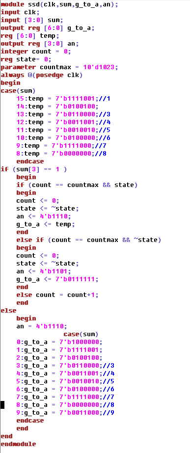
Figure 2-1: SSD module to display output for adder/subtractor
This module is similar to other labs. If the MSB of the final sum from
the module shown if Figure 1-1 is 0, the result is positive and the
number is simply shown on one of the SSD panels. If the MSB is one the
number is negitive. Now two panels must be switched between quickly to
show both a digit and negitive sign. Because vivado interprates numbers
not as their twos compliment, the case statment for negitive numbers is
modified. When placing the case statment inside the if statment to
display the digit, an unexpected error occured where the number was
never written to the ssd. For a less neat but functional solution, a
temp variable was used to store the value of every result interprited
as 2's compliment rather than just the negitive results. The ssd is
assigned the temp variable only when the number is negitive.
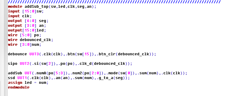
Figure 2-2: Testbench for SSD adder and subtractor
The output from the adder/subtractor module is is connected to the ssd.
To modify this testbench for section one simply connect sum to led
instead of a wire.
Video 2-1: SSD display added to 2 bit adder/subtractor
Task 3: Use SIPO to input data
with switch as a clock(30 points).
Figure 3-1: SIPO added module
This code is the same as the previously uploaded quiz.
Figure 3-1: SIPO updated testbench
This task was, unexpectidly, extreamly difficult. The poor quality of
the switches on the BAYSYS 3 board created large error in the clock
signals that was difficult to troubleshoot even with debouncing. After
a lot of troubleshooting I was able to pinpoint 2, maybe 3 issues. One
issue is that after a switch, the signal would bounce for a very long
time. Oftern upwaerds of a second of sharp bouncing signal. Once
pinpointed this was fixed by adjusting the debounce module to delay one
second. Another issue was the clock signal would trigger before even
touching the switch (I have no idea how this is even possable but it is
shown in Video 3-1). This was partially fixed by moving the clock
switch to the other side of the board as the SI switch. The circut
still was not working properly and would occasionally read in all
serial values at once. The only issue I could think is that the rising
edge from the switch is not sharp enough to only trigger the always
@(posedge clk) statment once. I have no idea if this makes sense but it
would explain it. Despite these issues, with the previously mentioned
fixes implimented the board would work as intendend most of the time, a
demonstration confirming the logic is shown in Video 3-2.
Video 3-1: Demonstration of glitching effect with switch
The counter variable for the SIPO module was tied to LED's 10 and 11.
You can see the counter is getting randomly changed without any flip of
the switch. This was with Dr.Li's code. The clock signal was also tied
to the leftmost LED and is also randomly updated.
Video 3-2: Demo of working 3 bit 2's compliment adder with SIPO and SSD
Conclusion: Using a switch as a clock signal created a lot of issues, but provided good troubleshooting experience