Name: Ian Van Horn Email: imvanhorn1@gmail.com
HW 7
This
homework introduces UART communication
This lab requires vivado, arduino IDE, and Tera Terminal
Task 1: Counter with Debounce.(25 points).
*This task was used as a quiz, the code in mostly re-used form the quiz
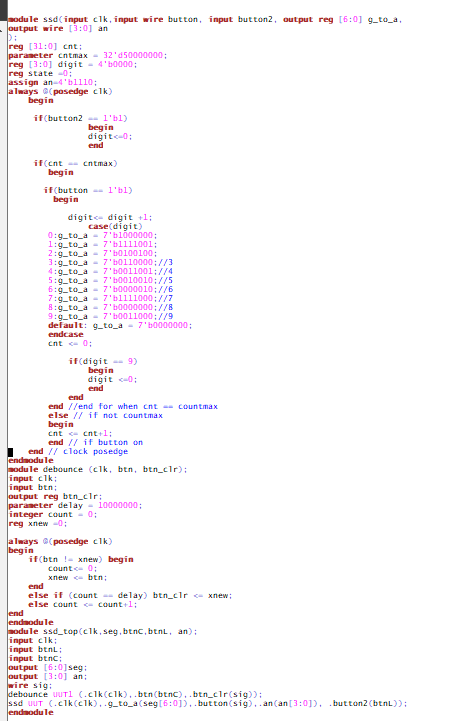
Figure 1-1: Counter code
The debounce module stops the button from showing many fast (bounce)
signals for each press. If the appropriate count has passed and the
button is pressed, digit is incrimented and a case statment is used to
assign the correct segments on the ssd to the correct value.
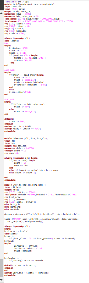
A UART package carries 11 bits. 8 data bits, a stop,start, and a parity
bit. When idle the transmitter is at 1. To start a package transmittion
the signal is pulled low. The 9 bits of information are transmitted,
then the signal is pulled high again.
The baud rate is the rate that information is transmitted. txData holds
a sandwhich of "data" and the high and low start/end signal. No parity
bit is used. The LOAD_BIT state loads each bit of the tx data into the
txBit, which is assigned to uart_tx.
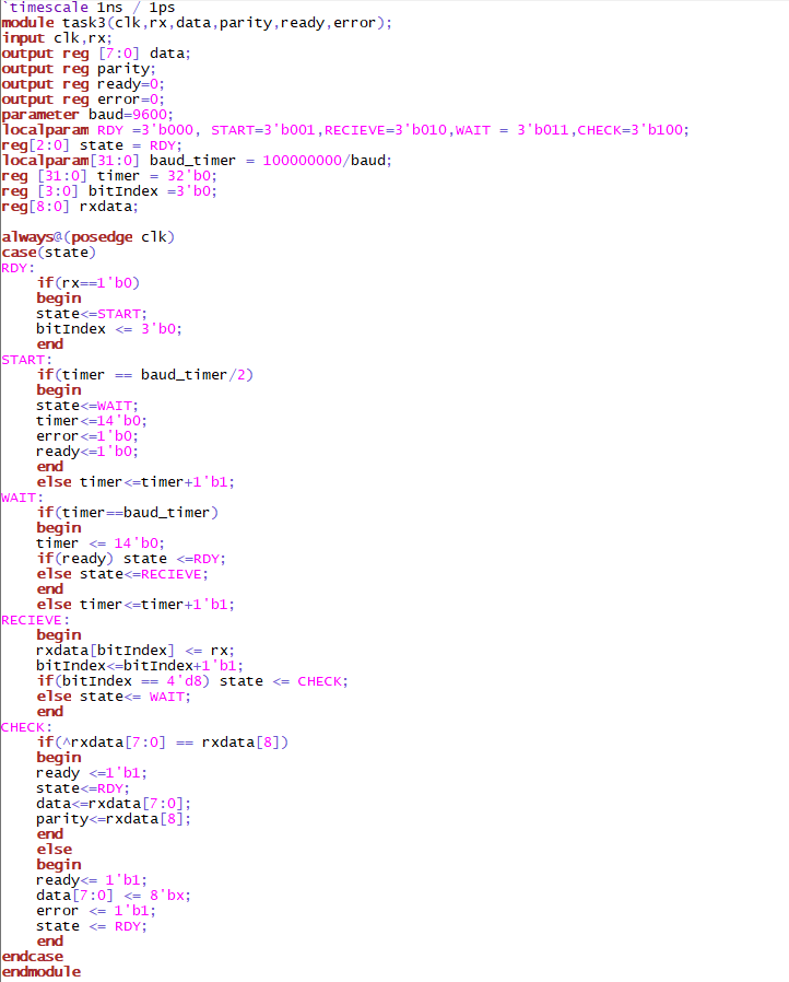
If the rx signal is pulled low, signaling the start of transmission,
RDY passes the state to START. Timer is incrimented until half of the
baud rate in START so the timer counts to baud_timer in the middle of
the next bit. At the appropriate time the state is passed to WAIT. When
reading data, SIPO register is used, rx is assigned to an address in
rxdata. Then an xor statment is used to check the parity bit.
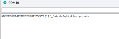
Figure 3-2: Demo of UART reciever
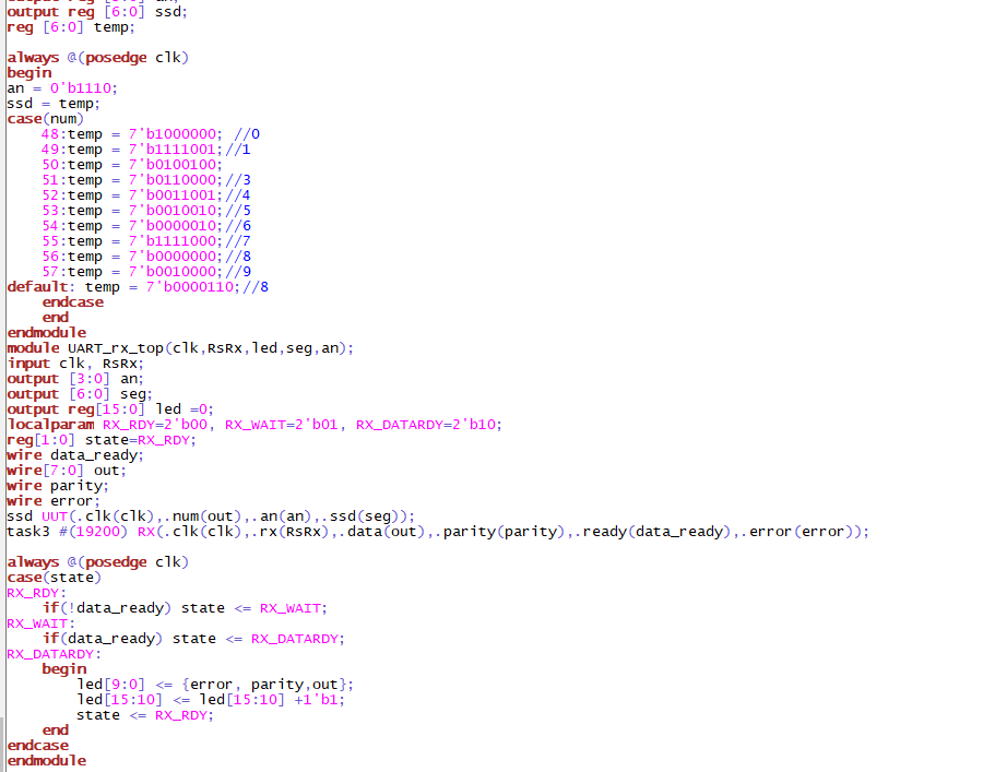
Task 4: UART reciever with SSD (25 points).
Figure 4-1: Code to add SSD to UART reciever
In the testbench, the wire "out" holds the value of the recieved char.
A switch statment is made to display the correct digit on the SSD based
on the recieved ASCII code. When the recieved code was not for a digit,
E was displayed. IMPORTANT: The parity generator from Tera
Terminal did not work for some reason, when set to even, any charcter
with an even number of 1's threw a parity error. When set to odd, the
same happened with numbers with an odd number of 1's. When disabled the
code worked as expected
Video 4-1: Demo of SSD
Conclusion: The Tera Terminal caused some confusion, but overall the UART implimentation went smoothly.